


39/42
SK5W7J-19A361-AA
© Copyright Ford 2005
2W7Z-16A901-AA
Rev Date- 8/29/05
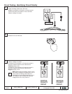
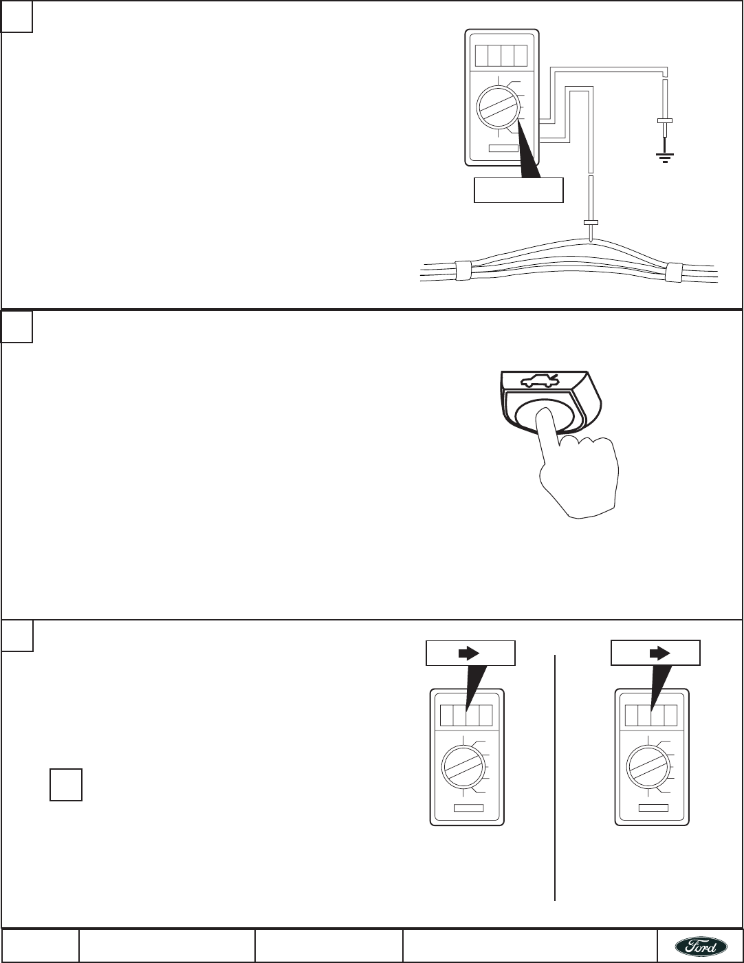
Circuit Testing - Identifying Circuit Polarity
1
DC Volts
Digital Volt Meter (DVM) set to “DC Volts”.
Negative lead (Black) connected to a chassis ground.
Positive lead (Red) connected to circuit under test.
Observe reading from meter.
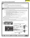
2
Actuate the circuit under test.
Observe reading from meter.
A reading of 0V transiting to +12V when the switch is
pressed, indicates that the circuit under test is a
Positive polarity circuit.
A reading of +12V transiting to 0V when the switch is
pressed, indicates that the circuit under test is a
Negative polarity circuit.
NOTE: When testing a Negative polarity circuit,
the stand by voltage will not always be +12V. In
some cases the reading observed prior to
actuating the circuit could be less than one (1)
volt. However, when actuated the observed
voltage will be 0V or very close to it.
3
!
0V
12V
POSITIVE
POLARITY
CIRCUIT
0V
12V
NEGATIVE
POLARITY
CIRCUIT