


Maintenance
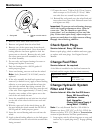
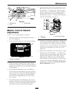
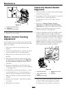
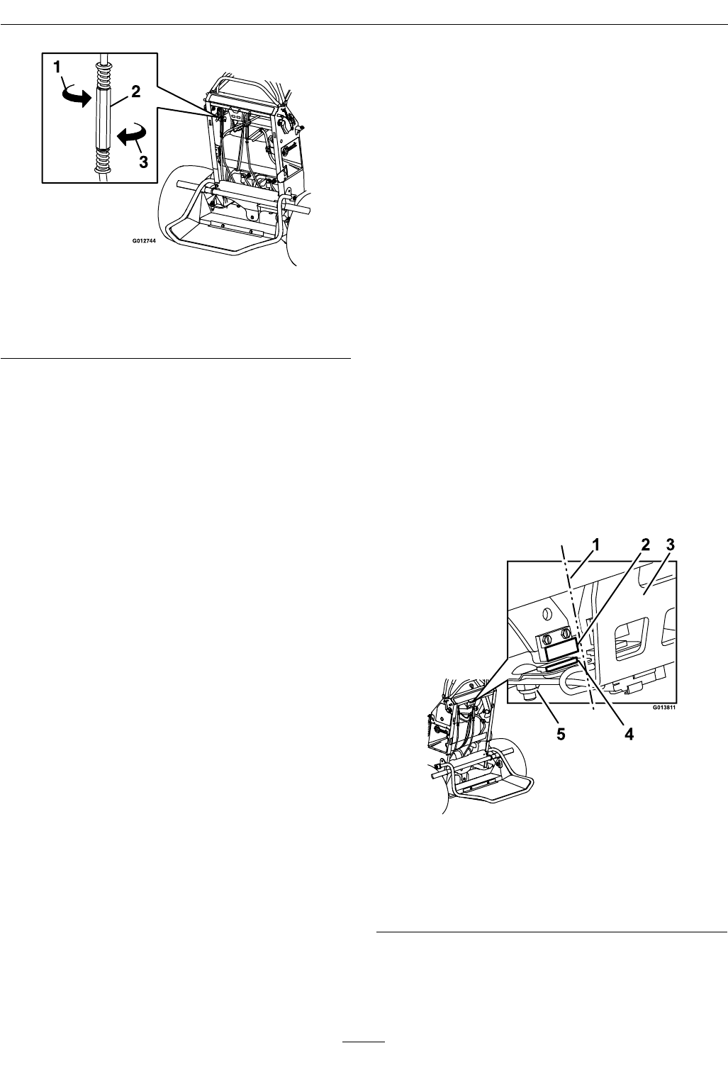
Figure 33
1. Rotate to increase speed
2. Turnbuckle
3. Rotate to decrease speed
9. Reinstall the rear cushion.
Motion Control Tracking
Adjustment
If the machine travels or pulls to one side when the
motion control levers are in the full forward position,
adjust the tracking.
1. Push both control levers forward the same
distance.
2. Check if the machine pulls to one side. If it does,
stop the machine and set the parking brake.
3. Release the rear cushion from the rear of the
machine.
4. Place the front reference/speed control bar in
the maximum forward position. See Adjusting
the Front Reference/Speed Control Bar in
Operation.
5. Rotate the turnbuckle on the LH side of the
machine (as viewed from the rear of the machine
— see Figure 33).
6. Looking down towards the turnbuckle — rotate
it counterclockwise, in 1/4 turn increments, to
increase speed or clockwise to decrease speed.
7. Drive the machine and check the full forward
tracking.
8. Repeat steps 5 through 7 until desired tracking
is obtained.
9. Reinstall the rear cushion.
Check the Neutral Switch
Alignment
1. Park the machine on a level surface and disengage
the blade control switch.
2. Stop engine, wait for all moving parts to stop, and
remove the key or spark plug wire(s).
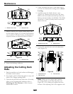
3. Set the height of cut to the 3 inch (7.6 cm)
position.
4. Perform the Motion Control Neutral
Adjustment and Motion Control Tracking
Adjustment as stated in the Maintenance section.
5. Release the rear cushion from the rear of the
machine and lower to the platform.
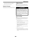
6. Check the alignment on the LH and RH neutral
switches upper and lower surfaces (reference
Figure 34). If they are not in alignment, loosen the
hardware on the lower neutral switch and adjust it
forward or rearward as necessary. Once aligned,
tighten the hardware. Check the neutral switch
alignment again as the deck is moved through the
highest and lowest cut height setting; adjust the
lower neutral switch surface if necessary.
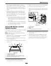
Figure 34
1. Alignment reference
4. Lower neutral switch
surface
2. Upper neutral switch
surface
5. Hardware
3. Switch mounting plate
7. Adjust the upper neutral switch surface left
or right if side-to-side alignment is needed.
The upper and lower switches should be as
40