


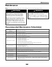
Maintenance
2. Carefully clean area around lter. It is important
that no dirt or contamination enter hydraulic
system.
3. Unscrew lter to remove and allow oil to drain
from reservoir.
Important: Before reinstalling new lter, ll
it with Exmark Premium Hydro oil and apply
a thin coat of oil on the surface of the rubber
seal.
Turn lter clockwise until rubber seal contacts the
lter adapter, then tighten the lter an additional
2/3 to 3/4 turn.
4. Fill reservoir as stated in Check Hydraulic Oil
Level.
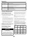
Exmark Premium Hydro Oil is recommended.
Refer to the chart for an acceptable alternative:
Hydro Oil
Change Interval
Exmark Premium Hydro
Oil (Preferred)
500 Hours
Mobil 1 15W50
250 Hours
5. Loosen lter 1/2 turn and allow a small amount
of oil to leak from the oil lter (this allows air to
be purged from the oil lter and supply hose from
the hydraulic reservoir). Turn lter clockwise
until rubber seal contacts the lter adapter. Then
tighten the lter an additional 2/3 to 3/4 turn.
6. Raise the rear of machine up and support with
jack stands (or equivalent support) just high
enough to allow drive wheels to turn freely.
CAUTION
Raising the mower deck for service or
maintenance relying solely on mechanical
or hydraulic jacks could be dangerous. The
mechanical or hydraulic jacks may not be
enough support or may malfunction allowing
the unit to fall, which could cause injury.
Do Not rely solely on mechanical or hydraulic
jacks for support. Use adequate jack stands
or equivalent support.
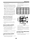
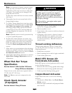
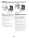
7. If either drive wheel does not rotate, one or both
of the charge pumps (located on the top of the
main pump as shown in Figure 21) may have lost
their “prime”. Refer to Hydraulic System Air
Purge section.
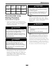
Note: Do Not change hydraulic system oil (except
for what can be drained when changing lter), unless
it is felt the oil has been contaminated or been
extremely hot.
Changing oil unnecessarily could damage hydraulic
system by introducing contaminates into the system.
Hydraulic System Air Purge
Service Interval: As required
Air must be purged from the hydraulic system
when any hydraulic components, including oil
lter, are removed or any of the hydraulic lines are
disconnected.
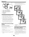
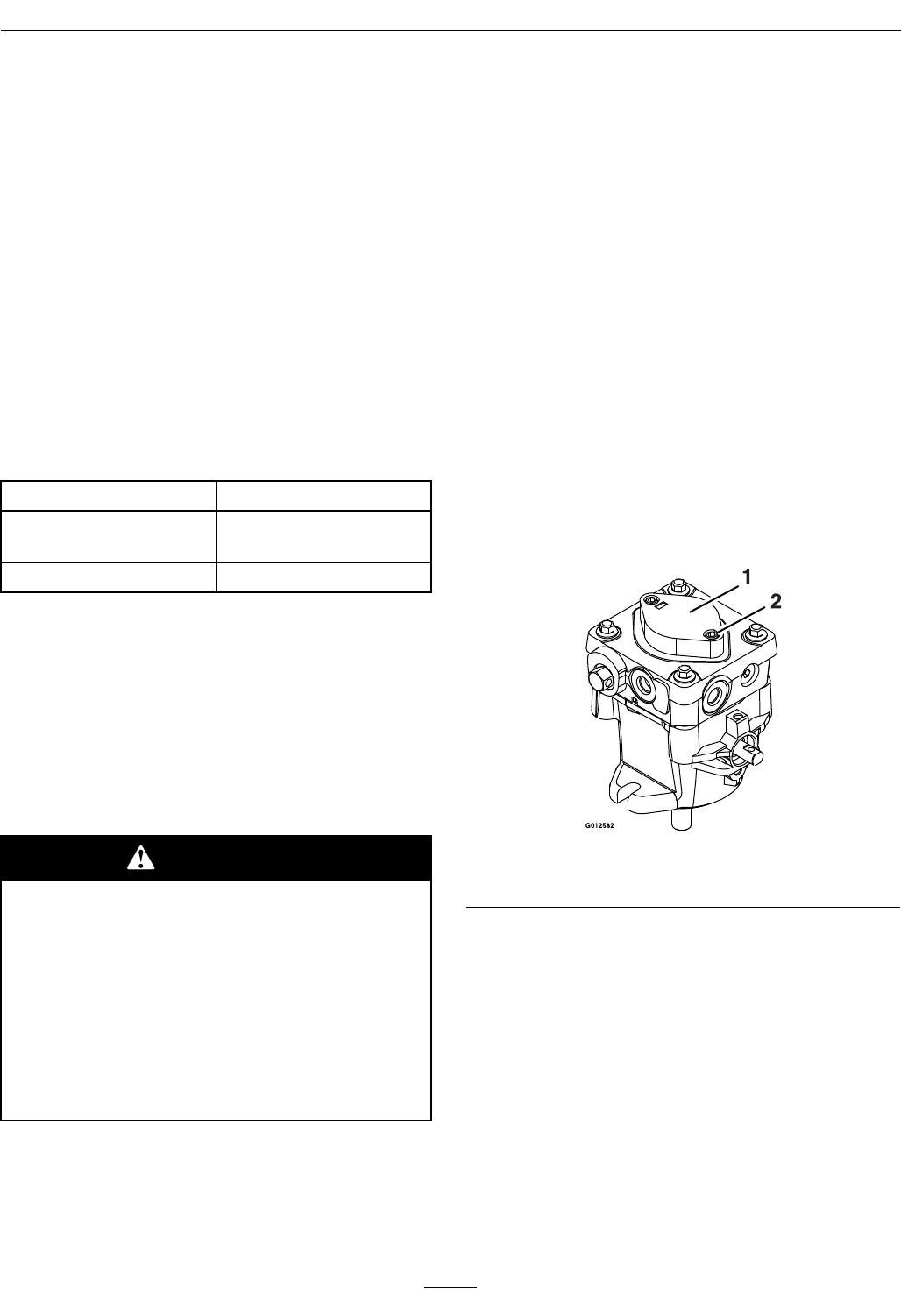
The critical area for purging air from the hydraulic
system is between the oil reservoir and each
charge pump located on the top of each variable
displacement pump (Figure 21). Air in other parts of
the hydraulic system will be purged through normal
operation once the charge pump is “primed”.
Figure 21
1. Charge pump cap 2. Loosen 1 1/2 turns only
1. Stop engine and wait for all moving parts to stop.
Raise the rear of the machine up onto jack stands
high enough to raise the drive wheels off the
ground.
2. Check oil level as stated in Check Hydraulic Oil
Level section.
3. Start engine and move throttle control ahead to
full throttle position. Move RH motion control
lever inward (together) and move both levers
forward with equal pressure.
If either drive wheel does not rotate, it is possible
to assist the purging of the charge pump by
carefully rotating the tire in the forward position.
33