


5
English
DOC.ATX.EL.1 Rev.: - May ‘03
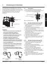
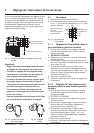
4 Limit Switch Settings
The end of travel limit switches have been factory set
for approximately 90° of valve travel. They will however
coincide with the exact end of valve travel positions.
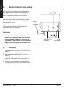
The switches and their operating cams are located
under the limit switch bracket which is fixed to the top
of the motor.
Important
* Set mechanical stops before setting limit
switches.
* The switches should be adjusted after the
actuator is installed on the valve and after the
mechanical stops have been set.
* The motor is de-energized once the flatted side
of the cam is in contact with the limit switch
actuator arm, and the switch is no longer
depressed.
* Capacitor may be removed from the limit switch
bracket for better access.
* For more precise setting you can leave the allen
wrench in the cam during setting procedure.
4.1 Procedure
1 Remove actuator cover.
2 The limit switches are marked “1” for close and “2”
for open.
4.1.1 CCW (Open) switch setting
3 Manually or electrically rotate actuator/valve to the
desired position.
4 REMOVE ELECTRICAL POWER.
5 Using a 2mm allen wrench loosen set screw on
cam.
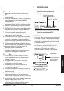
6 Rotate green cam until switch lever arm rides on
the curved portion of the cam. (fig 1d).
7 Rotate cam counter-clockwise until the switch
trips.
This can be detected by a slight audible “click”, or
use a battery powered test light across terminal 8
and 10.
8 Tighten set screws.
9 Electrically cycle the actuator to check switch
setting.
4.1.2 CW (Close) limit switch setting
10 Manually or electrically rotate actuator/valve to the
desired position.
11 REMOVE ELECTRICAL POWER.
12 Using a 2mm allen wrench loosen set screw on
cam.
13 Rotate red cam until switch lever arm rides on the
curved portion of the cam (fig 1d).
14 Rotate cam clockwise until the switch trips. This
can be detected by a slight audible “click”, or use a
battery powered test light across terminal 5 and 7.
15 Tighten set screws.
16 Electrically cycle the actuator to check switch
settings.
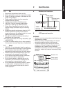
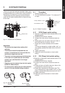
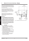
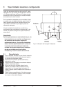
1 CLOSED (red)
2 Open (green)
3 (gray)
4 (gray)
fig. 4.1. Location of Limit Switches
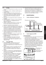
fig. 4.2. Switch Break
Position
fig. 4.3. Initial
Position
fig. 4.4 Switch Functions.
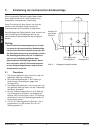
Limit switches
and cams
Indicator shaft
Primary Switches / cams
Extra Switches / cams