


4DOC.ATX.EL.1 Rev.: - May ‘03
English
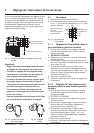
3 Mechanical Limit stop setting
All El-series electric actuators are equipped with a
manual override feature and a Stroke Adjustment
System. The purpose of this system is to limit the
stroke of the valve while under manual control.
On torque switch equipped actuators the limit stops
may be used to provide a greater degree of stroke
precision than by limit switches. ie. for high perfor-
mance butterfly valves.
After the actuator has been fitted on a valve and the
end of travel limit switches have been set, the
mechanical stops can be set as
follows:
Important.
* For torque seated applications the mechanical
stops do not need setting in the positions that
torque seating is required and the stop screws
should be backed off approx. 2 turns from the
fully closed or open position. This to prevent the
torque switch from tripping on the stop screws
and not on the valve seat.
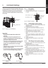
3.1 Procedure
1 With actuator mounted to a valve, electrically or
manually move the valve away from the fully open
position.
2 Turn the open stop screw out (ccw) 4 turns.
3 Manually operate the actuator to the full open
position.
4 Now turn the open stop screw in (cw) until an
obstruction is felt (do not force) then backoff 1/2
turn and lock the stop screw with the locknut.
5 Follow the same procedure at the closed end of
travel and adjust the “close” stop screw the same
way.
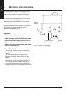
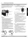
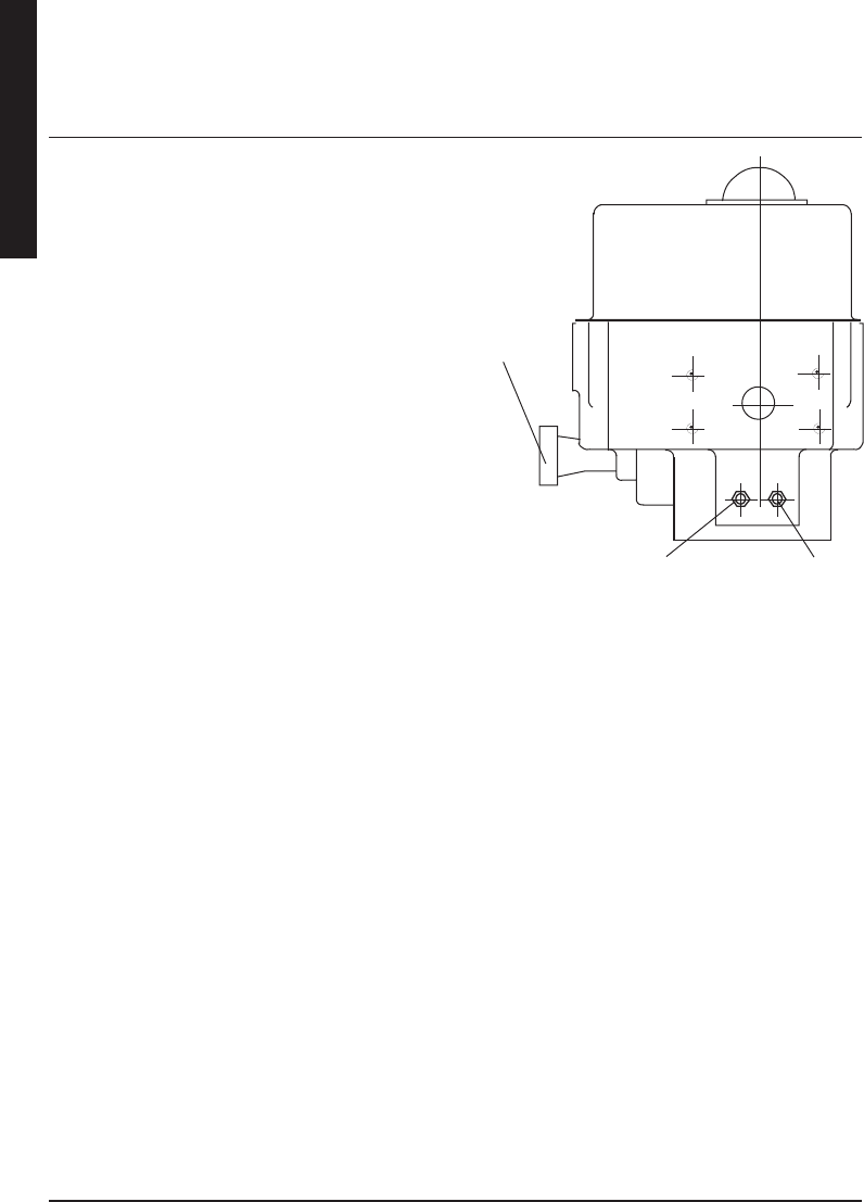
OPEN (Counter
Clockwise)
CLOSE
(Clockwise)
Manual
override
handwheel
Fig 3.1 Location of Limit Stops