


8
© 2003 directed electronics, inc.
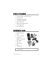
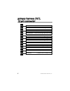
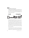
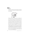
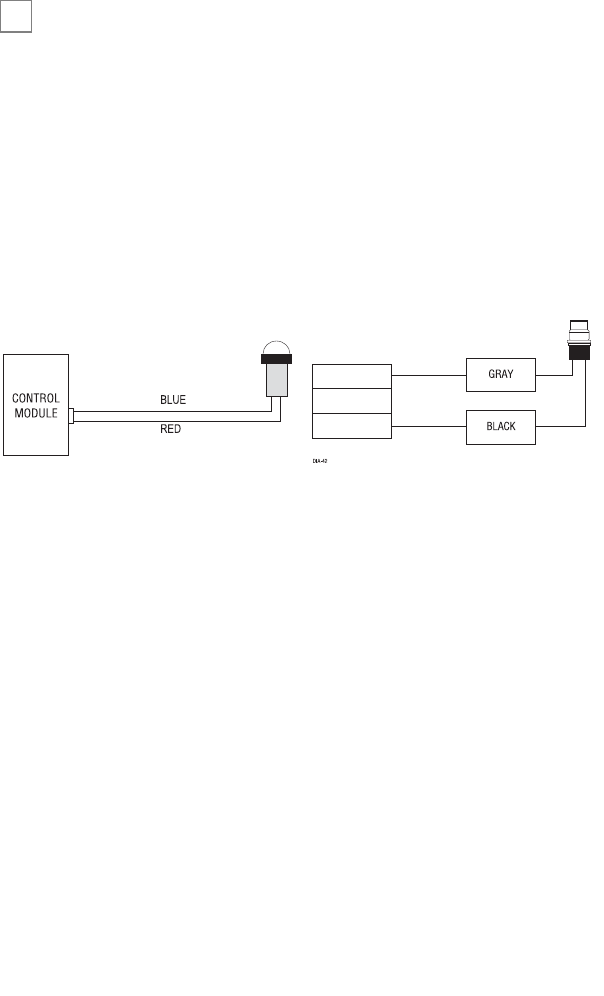
step 1
Plug-in LED and
Valet
®
/Program
switch
The LED and the Valet
®
/Program switch both plug into the
control module. The status LED plugs into the white two-pin
port, while the Valet
®
/Program switch should be plugged into the
blue two-pin port. The status LED and Valet
®
/Program switch
each fit into 9/32-inch holes.
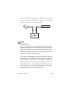
SSttaattuuss LLEEDD VVaalleett
®
//PPrrooggrraamm SSwwiittcchh
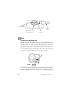
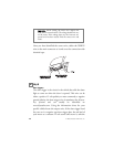
When mounting the LED it will be necessary to locate an area on
the dash that is visible from all sides of the vehicle, and has at
least 1 inch of clearance behind the mounting area. It is recom-
mended that a factory "pop-out" be used for the LED mounting,
using a 9/32 drill bit drill a hole in the location selected, feed the
LED through the hole, press the LED firmly until it snaps into
place. Run the wires to the selected control module mounting
location using caution to NOT run the wires near any moving
objects or excessive heat.
The Valet
®
/Program switch is usually mounted under the dash or
in the glove box, the same precautions used for the LED should
be followed. Once a location has been selected drill a 9/32 hole,
DIA-41
➜