


28
© 2003 directed electronics, inc.
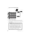
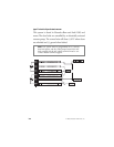
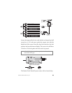
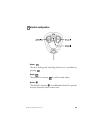
TTWWOO--RREESSIISSTTOORR TTYYPPEE::
If two resistors are used in the factory
door lock switch/key cylinder, the door lock switch/key cylinder
will read resistance to ground in both directions.
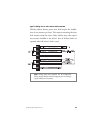
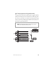
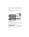
DDEETTEERRMMIINNIINNGG TTHHEE PPRROOPPEERR RREESSIISSTTOORR VVAALLUUEESS::
To
determine the resistor values, the door lock switch/key cylinder
must be isolated from the factory door lock system. For testing, use
a calibrated digital multimeter that is set to ohms.
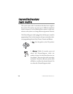
IIMMPPOORRTTAANNTT::
To ensure an accurate resistance reading, do not touch
the resistor or leads during testing.
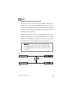
1. Cut the output wire from the door lock switch/key cylinder in
half.
2. Test with the meter from the switch side of the cut door lock
switch/key cylinder wire to a reliable ground source. Some good
ground references are the ground input source to the door lock
switch/key cylinder or the battery ground.
3. Operate the door lock switch/key cylinder in both directions to
determine the resistor values. If the multimeter displays zero
resistance in one direction, no resistor is needed for that direc-
tion.
4. Once the resistor value(s) is determined, refer to the wiring dia-
gram for proper wiring.