


8
© 2003 directed electronics, inc.
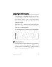
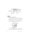
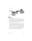
step 1
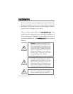
Plug-in LED and Valet/Program switch
The LED and the Valet®/Program switch both plug into the
control module. The status LED plugs into the white two-pin
port, while the Valet®/Program switch should be plugged into
the blue two-pin port. The status LED and Valet®/Program
switch each fit into
9
/
32
–inch holes.
SSttaattuuss LLEEDD VVaalleett//PPrrooggrraamm SSwwiittcchh
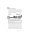
When mounting the LED it will be necessary to locate an area on
the dash that is visible from all sides of the vehicle, and has at
least 1 inch of clearance behind the mounting area. It is recom-
mended that a factory "pop-out" be used for the LED mounting,
using a 9/32 drill bit drill a hole in the location selected, feed the
LED through the hole, press the LED firmly until it snaps into
place. Run the wires to the selected control module mounting
note: The security features consist only of ignition watch
where the horn will honk if the keyless system sees igni-
tion when locked and the security feature is turned on in
the features learned routine.
DIA-41
➜