


9
© 2003 directed electronics, inc.
location using caution to NOT run the wires near any moving
objects or excessive heat.
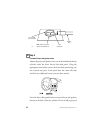
The Valet®/Program switch is usually mounted under the dash
or in the glove box, the same precautions used for the LED
should be followed. Once a location has been selected drill a
9/32 hole, feed the wires through the hole and press the switch
firmly until it snaps into place. Run the wires to the same loca-
tion as the LED using caution to NOT run the wires near any
moving objects or excessive heat.
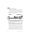
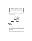
step 2
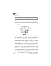
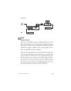
Ground Wire
The BLACK (H1/8) wire on the main 8-pin harness is ground.
This wire should be connected to a clean, paint-free area of metal
in the drivers kick panel area. First strip back a ¾-inch section of
the insulation off the BLACK wire and crimp a ring terminal
(not provided) to that wire. Locate a clean, paint-free metal
surface in the drivers kick panel. Using a self-tapping screw, drill
the screw with the ring terminal to the metal area. Once screwed
down, pull on the wire to ensure a good connection.
note: More problems are attributed to poor ground con-
nections than any other cause. Take extra care to ensure
the ground is clean and secure.
➜