


11
© 2003 directed electronics, inc.
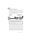
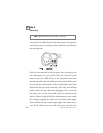
thicker wires. With the ignition harness exposed, use your digital
multi-meter to find your power and ignition wires.
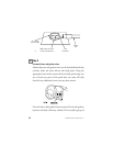
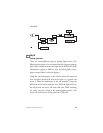
Place the black lead of the meter to a clean metal surface in the
kick panel area and secure it. Put the meter in the DC voltage
position, then take the red lead of the meter and probe one of the
thicker gauge wires. The color and identity of your specific
vehicle wiring can be obtained at www.diyrattler.com. With the
key in the OFF position, test the suspect wire. The constant
power wire will read between 11.00 volts and 13.00 volts.
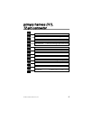
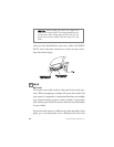
Once the constant power wire has been identified, solder the
RED (H1/11) wire from the 12-pin harness to it and cover the
connection with electrical tape to ensure a safe connection.
With the meter black lead still in the kick panel, locate the igni-
tion wire harness in the same location. It will test differently than
constant (+)12 volts. Locate the suspected wire using the
www.diyrattler.com Web site and place the red lead of the meter
on the suspected wire. With the key in the off position the meter
will read 0.00 volts. Turn the key to the on position and the meter
should read between 11.00 volts and 13.00 volts. Now watching
the meter, turn the key to the crank position and the voltage
should drop a small amount but not disappear. If the voltage
disappears this is not an ignition wire but an accessory wire. If the
wire meters correctly, solder the YELLOW (H1/9) wire from the
12-pin harness to it and cover the connection with electrical tape.