


4
©
2005
Directed Electronics, Inc. all rights reserved
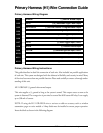
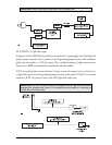
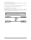
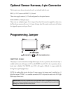
Primary Harness (H1) Wire Connection Guide
Primary Harness Wiring Diagram
___
___
___
___
___
___
___
___
___
___
___
___
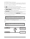
Primary Harness Wiring Instructions
This guide describes in detail the connection of each wire. Also included are possible applications
of each wire. This system was designed with the ultimate in flexibility and security in mind. Many
of the wires have more than one possible function. Please read carefully to ensure a thorough under-
standing of this unit.
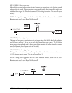
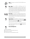
H1/1 ORANGE (-) ground-when-armed output
This wire supplies a (-) ground as long as the system is armed. This output ceases as soon as the
system is disarmed. The orange wire is pre-wired to control the 8618 starter kill relay. It can supply
up to 500 mA of current.
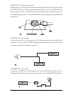
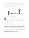
NOTE: If using the H1/1 ORANGE wire to activate an add-on accessory such as window
automation, pager or voice module a 1Amp diode must be installed to ensure proper operation.
Insert the diode as shown in the following diagram.
RED/WHITE (-) 200 mA Channel 2 Output
RED (+) Constant Power Input
BROWN (+) Siren Output
YELLOW (+) Switched Ignition Input, Zone 5
BLACK (-) Chassis Ground Input
VIOLET (+) Door Trigger Input, Zone 3
BLUE (-) Instant Trigger Input, Zone 1
GREEN (-) Door Trigger Input, Zone 3
BLACK/WHITE (-) 200 mA Domelight Supervision Output
WHITE/BLUE (-) 200 mA Channel 3 Programmable Output
WHITE (+)/(-) Selectable Light Flash Output
ORANGE (-) 500 mA Armed Output
H1/1
H1/2
H1/3
H1/4
H1/5
H1/6
H1/7
H1/8
H1/9
H1/10
H1/11
H1/12