


6
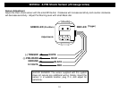
WIRING: 9-PIN Connector Cont.
Blue/White: (-) Passenger Door Unlock Output (Optional, requires relay)
This wire activates when the unlock button on the remote is pressed a second time within 15 seconds upon
disarming. This wire is used for the Optional Separate Driver’s/Passenger Unlock feature. Connects to unlock
circuit for passenger door or doors. See DOOR LOCK WIRING for special configuration options (page 14).
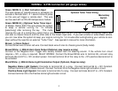
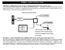
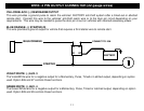
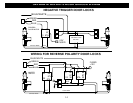
Orange: (-) Negative Starter Disable/Anti-Grind Output
This wire should be connected to the Yellow wire of the pre-wired relay socket for the starter disable. Connect the
blue wire of the relay socket to the Ignition switched wire on the vehicle. Cut the vehicle starter wire and connect
each half to an Orange wire on the relay socket. This output also turns on with remote start to function as an “Anti
Grind” wire to prevent the starter from grinding if you get in your car and turn the key too far after it was remote
started. See starter disable diagram on next page.
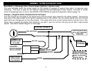
CUT
STARTER WIRE
STARTER
ORANGE
ORANGE
CONNECT TO
PRE-WIRED
OF ALARM
IGN. SWITCHED
BLUE
YELLOW
ORANGE WIRE
STARTER DISABLE
RELAY & SOCKET
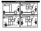
IGNITION SWITCHED
"ON" & HOT THROUGH
CRANKING
BROWN
START OUTPUT
6-PIN HARNESS
FROM ALARM
MAKE CERTAIN TO
CONNECT BROWN
WIRE TO STARTER
MOTOR SIDE!!!
STARTER DISABLE: