


27
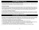
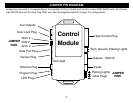
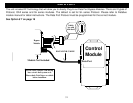
JUMPER PIN DIAGRAM
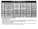
Jumper pins are used to change/configure the operation of the on board multi-function output PINK WHITE wire, the Parking
Light WHITE wire and the Glow Plug PINK wire. See the diagrams below for Jumper Pin configurations.
Parking Lights
Start 2
IGN 2
ACC 2
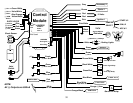
Control
Module
High Current Plug
Antenna Plug
Data Port Plug
Program Plug
Not Used
LED Plug
Door Lock Plug
JUMPER
PINS
JUMPER
PINS
Glow Plugs
Outputs - 500mA
Inputs
Tach, Ground, Parking Lights
Sensor Plug
Aux Outputs