


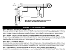

wire is used, the RS900/901/999FM system will wait until light turns off before attempting a remote start. Note: This
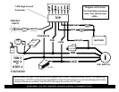
input is jumper selectable for Positive or Negative type signals. See system wiring diagram for jumper configuration.
PIN 8: PURPLE: (+12V) BRAKE RESET
Connect the Purple wire to the side of brake pedal switch that shows +12 volts ONLY when pedal is depressed.
This is the wire that turns off the remote start once the driver’s key is in the Ignition and turned to the ON position.
PIN 9: ORANGE/BLACK: (-) OEM DISARM OUTPUT
This wire provides a Ground pulse to disarm the vehicles' Factory anti-theft system prior to a Remote Start. Connect this
wire to the vehicles' anti-theft disarm wire. This wire is sometimes found coming off the Driver's door key switch or at the
Factory Anti-theft control module. This wire may not be needed if Factory Security only requires a door unlock pulse.
PIN 10: ORANGE: (-) OEM REARM OUTPUT
This wire provides a ground pulse to rearm the vehicles' FACTORY anti-theft system after a timed-out or aborted remote
start. Connect this wire to the vehicles' anti-theft rearm wire or to the door pin circuit depending on your requirements.
This wire may be needed to pulse the door pin circuit on vehicles with retained accessory power.
PIN 12: RED/WHITE: TACHOMETER INPUT
When installing the RS900/901/999FM in Tach mode, this wire must be connected to a valid source of AC voltage. This
wire allows the unit to sense the engine running and control the starter motor. See TACH REFERENCE MODE for
more.
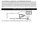
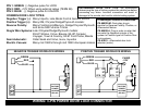
WIRING: 2-PIN LED / 2-PIN PROGRAMMING BUTTON
PROGRAM/OVERRIDE SWITCH: 2 PIN PLUG
This switch is used for programming features, transmitters, valet mode, and to override the optional starter disable (if
installed) in the event of a non-operating remote control.
LED: 2 PIN PLUG (OPTIONAL)
The LED is used as a VALET/PROGRAMMING indicator and it will also FLASH for use as security deterrent when the
optional ANTI-GRIND/STARTER DISABLE output is programmed.
WIRING: 7-PIN HIGH-CURRENT CONNECTOR
BROWN: +12V STARTER OUTPUT 30A:
Connect to circuit in the vehicle that has power ONLY during STARTER MOTOR CRANKING.
GRAY: +12V ACCESSORY OUTPUT 30A:
Connect to circuit in the vehicle that provides Accessory Power for systems such as HEAT and A/C. Typically, this wire
turns ON with the first position of the key, DROPS OUT WHEN CRANKING, then returns as the engine starts and runs.