


PLAN OUT YOUR INSTALLATION and determine most suitable locations for all components to be placed. These
components include: the module itself, valet/program button, possible relays, and antenna/receiver (RS900/999FM only,
RS901 model does not include antenna or remotes.) Allow enough wire to create a service loop with strain relief, should
servicing be required. This will also allow easier access and mounting.
DAMAGE to the CoolStart unit resulting from incorrect installation or failure to follow guidelines stated in this book will
not be covered under warranty and subject to repair or replacement charges.
USE A VOLT/OHM METER to test and locate all connections. Test Lights can damage a vehicle’s computer systems.
ADDITIONAL PARTS, which are not included with this unit, may be needed for your particular vehicle. . These items
may include extra relays or Anti-Theft System Bypass modules.
INSTALLATION CAUTIONS & WARNINGS
**FOR SAFETY REASONS, DO NOT INSTALL RS900/901/999FM in vehicles with MANUAL TRANSMISSIONS.** If
accidentally left in gear, a remote started vehicle could become a self-propelled threat to life and property.
DO NOT extend the RS900/901/999FM Remote start ignition harness length. Mount the module so that main harness
reaches all ignition switch wiring. Extending these wires could result in poor performance.
DO NOT route any wiring that may become entangled with brake, and gas pedals, steering column, or any other moving
parts in the vehicle.
DO NOT exceed the rated output current of any circuit on the Remote start module. Failure to observe this warning will
result in damage to the unit not covered under warranty.
DO NOT remote start the vehicle in a closed garage. Make sure that the garage door is open or there is adequate
ventilation. Failure to observe this rule could result in injury or death from poisonous Carbon Monoxide fumes.
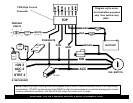
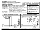
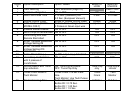
WIRING: 11-PIN CONNECTOR
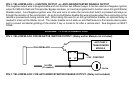
PIN 1: YELLOW/WHITE: (-) HORN CHIRP/HONK OUTPUT
Connect to the Negative Horn Trigger wire usually located near the steering column. If the vehicle horn circuit requires
+12V, then a relay is required. RELAY WIRING: Connect the Yellow/White wire to terminal 85, connect relay terminals
86 and 87 to +12V constant power. Connect terminal 30 of the relay to the +12V positive Horn activation wire.
PIN 2: BLACK: MAIN SYSTEM GROUND
Connect to chassis metal of the vehicle. An existing bolt or screw may provide an adequate ground, or drill a small hole,
scrape away paint and attach using a sheet metal screw & star washer. This wire must be connected to a proper ground
or undesirable and inconsistent operation will occur. Do not use Factory ground locations.