


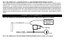
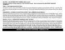
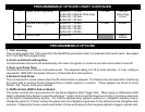

PIN 3: YELLOW/BLACK: (-) IGNITION OUTPUT -or- ANTI-GRIND/STARTER DISABLE OUTPUT
This negative output wire is programmable and can function two different ways. It can be used as a Negative Ignition
output for GM Anti-theft and Transponder Bypass modules, or it can be programmed to function as an Anti grind/Starter
Disable output. As a Negative Ignition wire, this wire turns on when the remote start button is pressed and stays on
through the duration of the remote start. As an Anti grind/Starter disable this wire activates when the Lock button on the
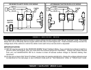
remote is pressed and during remote start. When using this wire for an Anti grind/Starter disable, an optional Relay is
needed to interrupt the Starter circuit. The starter disable circuit adds an anti-theft feature to this remote start system
and to prevent accidental grinding of the starter if key is turned to far after a remote start. See diagrams on NEXT
PAGE.
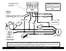
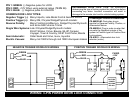
WIRING: 11-PIN CONNECTOR
PIN 3: YELLOW/BLACK FOR NEGATIVE IGNITION OUTPUT: (Relay and/or Module not included)
YELLOW/BLACK
85
86
30 87
3rd IGN
(If needed)
IGN SW.
OR
ANTI-THEFT/
MODULE
+12V CONSTANT
OR
TRANSPONDER
PIN 3: YELLOW/BLACK: FOR ANTI-GRIND/STARTER DISABLE OUTPUT: (Relay not included)