


mAI085-MB Actuator Interface Technical Manual /29
Distributive Intelligence
CMC INDUSTRIAL ELECTRONICS LTD
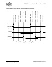
8. Using the Modbus Network Interface
The mAI085-MB incorporates a RTU Slave Mobus interface. This interface responds to only 3
Modbus slave commands. The commands are 3 - Read Holding Registers, 6 - Write One
Holding Register and 16 - Write Multiple Holding Registers. The Modbus protocol allows a
maximum of 125 Register Reads and 100 Register Writes in a single transaction. The following
tables provide the register assignments for the Modbus interface. The command register within
the interface mimics the operation of the front panel keys and discrete inputs.
8.1 The Modbus Serial Interface
The physical connection is by a RS-232 port. The unit has a DB9 female connector, wired as a
DCE device. A modem or pin to pin cable can be used to connect the unit to a standard DTE
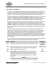
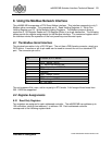
port. The connector pin-out is:
Pin Function at DTE device
1 DCD - always +9VDC
2 TX - data from mAI085-MB
3 RX - data to the mAI085-MB
4 DTR - not used
5 Common
6 DSR - always +9VDC
7 RTS - not used
8 CTS - always +9VDC
9 RI - not used
The unit supports 8 bit, even, odd or no parity in RTU mode. A full range of baud rates from
300 -19200 are supported.
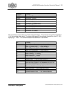
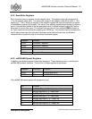
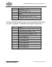
8.2 Register Assignments
8.2.1 Read Only Registers
Two registers are assigned to each addressed controller. The mAI085-MB can address up to
100 controllers, starting from address 1 to address 100. Each addressed controller
corresponds to the following register table: