


mAI085-MB Actuator Interface Technical Manual /25
Distributive Intelligence
CMC INDUSTRIAL ELECTRONICS LTD
6. The Input / Output System
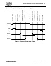
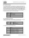
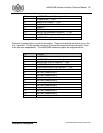
The mAI085-MB Actuator Interface has 4 discrete inputs and 4 discrete outputs. Figure 2 and
Table 2 detail the physical connections to the discrete signals. Each of the signals is described
below:
Name Description
Input 1
Pin 1
Energizing this input will select Open mode and turn on the OPEN indicator on the
front panel. Only the positive edge of the input signal is recognized and the input
must be de-energized between operations. Once energized, this input does not
affect front panel operator function.
Input 2
Pin 2
Energizing this input will select Close mode and turn on the CLOSE indicator on
the front panel. Only the positive edge of the input signal is recognized and the
input must be de-energized between operations. Once energized, this input does
not affect front panel operator function.
Input 3
Pin 3
Energizing this input will clear all of the actuators setpoints. The clear will occur
immediately. Only the positive edge of the input signal is recognized and the input
must be de-energized between operations. Once energized, this input does not
affect front panel operator function.
Input 4
Pin 4
Energizing this input forces all of the actuators closed immediately. The actuators
will remain closed regardless of the controller being in Open mode. Open/Close
mode is not affected by this input and the actuators will re-open when this input is
de-energized if the interface is in Open mode. Open/Close timers are ignored by
this input and the force close will override any timing function in progress.
Output 1
Pins 1 & 2
This output can have 2 functions depending on the setting of the oPL timer. If the
oPL timer is set to 0, this output will energize whenever the interface is in Open
mode. The output remains energized until the mode is changed to Close. If a
value has been entered into the oPL timer, this output will energize for the length
of time set by the oPL time, each time the Open mode is selected. This form of
operation can be used as a start signal for a conveying system.
Output 2
Pins 3 & 4
This output can have several functions depending on the setting of the cPL and
cDL timers. If the cPL timer is set to 0, this output will energize whenever the
interface is in Close mode. The output remains energized until the mode is
changed to Open. If a value has been entered into the cPL timer, this output will
energize for the length of time set by the cPL time, each time the Close mode is
selected. This form of operation can be used as a stop signal for a conveying
system. The energizing of this output will be delayed if a value other than 0 is set
in the oDL timer. The oDL timer can be used to purge a conveying system after
all of the actuator gates have been closed using the Close mode.