


14 15
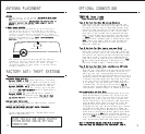
ANTENNA PLACEMENT
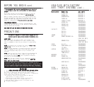
FACTORY ANTI-THEFT SYSTEMS
FOR GENERAL MOTORS CARS ONLY
System 1: PASSKEY or VATS system (1985 and up). This system
has a resistor pill in the key. Measure resistance of the pill
using a test meter. A bypass module is available, Module 791.
System 2: PASSLOCK I and II system (1995 and up). Passlock
does not have a pill in the key. It has a light on the dash
that states ANTI-THEFT OR SECURITY system. A bypass module is
available, Module 791.
System 3: PASSKEY III system (GM 1998 and up). Passkey III
is GMs version of a transponder system. This key will have
the letters PK3 on it. A bypass module is available. (Part
#791)
FORD ANTI-THEFT SYSTEM: PATS
1995-1998 Ford uses a bypass part #FBP-718 module. (1999 and
up will use part #791.)
CHRYSLER AND MOST IMPORTS ANTI-THEFT SYSTEM: TRANSPONDER
1998 and up will use part #791.
To order these bypass modules call 1-800-659-0764 or see our
website at www.jbstech.com.
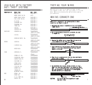
OPTIONAL CONNECTIONS
START VEHICLE AND CHECK STARTER
SYSTEM BEFORE ADDING OPTIONAL
CONNECTIONS.
TESTING: Door Locks
There are three basic types:
“Type A” Door Lock Test (Most GMs and some Chryslers)
Probe both of your door lock wires going to the door lock
switch usally located in the driver’s kick panel. Attach the
clip end of your test light to a good chassis ground. Using
the vehicle’s door lock controls, activate the lock then the
unlock, testing both wires one at a time. If one of these
wires tests (+) positive when lock is pressed and the other
tests (+) positive when they are unlocked, your vehicle has
a “Type A” door locking system. Make sure to mark which wire
is lock and unlock. Proceed to page 17, Connecting Door Locks.
NOTE: “Type A” and “Type C” locks will test the same, until
you test for ground. Make sure you run both tests before
making your connections.
“Type B” Door Lock Test (Most Imports, some newer Fords)
Probe both of your door lock wires going to the door lock
switch usally located in the driver’s kick panel. Attach the
clip end of your test light to +12V. Using the vehicle’s door
lock controls, activate the lock then the unlock testing both
wires one at a time. If the test light illuminates when you
probe the lock and the unlock wires your vehicle has a “Type
B” door locking system. Make sure to mark which wire is lock
and unlock. Proceed to page 17, Connecting Door Locks.
“Type C” Door Lock Test (Most Fords, some Chryslers, GM Trucks)
(Optional part #778 required)
Using your test light probe both the lock and the unlock wires
usually located in the driver’s kick panel. Attach the clip
end of your test light to ground probing both wires one at
a time while locking and unlocking the doors with the driver’s
side switch (usually the master switch). The test light should
illuminate in both switch positions. Now attach the clip end
of your test light to +12V constant, probe both wires one
at a time again. The light should then illuminate again only
in reverse order. This tells you that you have a “Type C”
reversing polarity system. Make sure to mark which wire is
lock and unlock. Proceed to page 17-18, Connecting Door Locks.
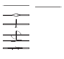
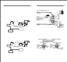
Testing Switch Wire and Motor Wires
Before connecting, you must now determine which wire is the
switch wire and which is the motor wire. Cut both the lock
and unlock wires in half. Start with both of the lock wires
by placing the clip end of your test light to ground, hold
the door lock switch in the lock position, make sure you are
using the master switch (usually on the driver’s door) and
probe both lock wires looking for voltage. The wire that
illuminates the test light, mark as the switch wire, the wire
that shows no voltage, mark as the motor wire. Repeat the
procedure for the unlock wire. When connecting the lock and
unlock wires to the #778 relay harness, make sure you connect
the switch wire to the RED wire or pin #87A and the motor
wire to the BLUE wire or pin #30. Be sure to connect the lock
wires to the lock relay, and the unlock wires to the unlock
relay, you may need to mark these relays before you start.
NOTE: IF YOUR VEHICLE REQUIRES A DUAL PULSE TO UNLOCK YOUR
POWER DOOR LOCKS, SEE PROGRAMMING “DUAL PULSE UNLOCK”, PAGE 19.
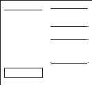
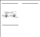
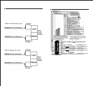
Control Module
Antenna Wire
E Model Antenna Tube
E MODEL REMOTE STARTERS
Run the antenna up the windshield pillar on the driver’s
side and across the top of the windshield to the center,
behind the rearview mirror. Use the antenna clips provided
to hold it in place. Be sure to expose the full length of
the clear antenna. It will perform best if mounted vertically,
below the dark windshield tint. Never leave antenna in
headliner. Range is up to 800 feet.
Each receiver is tested to more than 400 feet (800 feet,
E models) of clear air reception. While many times you will
see a higher range. Many factors will affect the range,
including the amount of radio signals in the area, battery
strength, window tint, etc.
ANTENNA
For best results, run the antenna (YELLOW WIRE WITH BLACK
TIP from the back of the unit) as high up in the dash and
as straight as possible. Do not place the antenna next to
any metal parts or the vehicle’s main computer control
module. Range is up to 400 feet.