


18 11
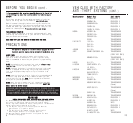
LOCATING & MAKING CONNECTIONS
AUXILIARY INPUT
If you wish to use this starter with an aftermarket
alarm, connect the BLUE wire from the 18-pin harness
to the second or third channel (-) output of your
existing alarm. When the output is activated, a (-)
signal will be supplied to the remote starter.
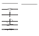
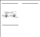
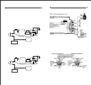
TRUNK RELEASE OUTPUT (-) (Optional Part #775 required)
Locate the trunk release wire coming from the back of the trunk
release switch. To determine if your trunk release is tripped by
a (+) positive or a (-) negative (most trunk release switches are
(+) positive), place the clip end of your test light to ground,
probe the wire. Press the “Trunk” button, if the test light
illuminates, you have a (+) positive trunk release. If it does
not, connect the clip end of the test light to +12V constant and
probe the wire. If the test light illuminates when the button is
pressed, then you have a (-) negative trunk release.
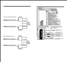
Connect the WHITE WITH RED STRIPE wire to the WHITE wire of the
optional relay. Please use figures below for correct connections.
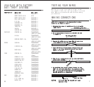
OPTIONAL CONNECTIONS
BRAKE INPUT (+)
The brake wire is located on the switch near and above the brake
pedal, if you cannot locate this wire at the brake switch, you will
then need to locate a wire at the rear window brake light or at the
brake light system in the rear of the vehicle. The correct wire will
show +12V only when the brake is pressed. Connect the BLUE WITH BLACK
STRIPE from the 18-pin harness to this wire.
FACTORY ALARM SHUT DOWN WIRE (FASD) (-)
If your vehicle is equipped with a factory alarm system (as most
vehicles with a factory keyless entry are) or, if your vehicle DOES
NOT have a factory remote control that honks the horn when locking
and unlocking the doors, or when you use the key in the driver’s door,
you DO NOT get a light on the dash that says “security” then mostly
you will not need to use this wire. If your vehicle is so equipped,
probe for a small gauge wire (usually found in the driver’s side kick
panel) that shows (-) ground when the door lock cylinder is turned
to the unlock position using the key. This wire will usually show a
(+) positive voltage before turning the key. NOTE: Some factory disarm
wires remain neutral before you turn the key to unlock instead of +12v
positive. Connect the RED WITH BLACK STRIPE wire from the 18-pin
harness to this wire.
HOOD PIN SWITCH (-)
This feature will keep the engine from starting, or shut off the
engine when the hood is opened (this is ONLY when in remote start
mode, this hoodpin switch has no control over an engine when started
with the ignition key or under normal operation). Locate a good
chassis ground, if at all possible do not install the pin switch in
the rain gutter. Drill a 5/16 hole, insert the pin switch into the
hole and tighten. Check for the hood adjustment, there is approximately
1/4” adjustment in the pin switch. Close the hood easy, making sure
that the pin switch is not keeping the hood from closing all the way,
if it does, cut off approximately 1/8” of the black plastic off of
the top of the hoodpin switch and try closing the hood again. Check
to make sure that the hoodpin switch remains neutral when the hood
is closed and shows ground when the hood is open. Plug the BLACK WITH
BLUE STRIPE wire from the 18-pin harness into the bottom of the hood
pin switch.
TACH INPUT (Optional)
By this time, you should have determined the way you want your vehicle
to start (tach or tachless). If you have chosen the TACHLESS start
option, simply proceed to the next step and skip the following
connection instructions. Make sure to tape the BLACK WITH WHITE STRIPE
wire up if not used. For TACH mode connect the BLACK WITH WHITE STRIPE
wire from the 18-pin harness to the negative side of the coil or the
tach wire at the coil pack under the hood. To find the coil pack
follow the spark plug wires back to the termination point. To operate
in tach mode, make sure to program tach option, see programming tach
option page 19.
OPERATOR PROGRAMMING INSTRUCTIONS
ENTERING PROGRAMMING MODE
Make sure your vehicle is not running and the brake is pressed.
The brake is to remain pressed as long as you want to remain
in programming mode. The only exception is when a different
remote has been learned. The unit will exit the programming
mode simply by releasing the brake and the parking lights will
flash three (3) times.
Adding Additional Remotes
with a Working Remote Control
Press and hold brake. Next, press and hold Button #1
on the working remote until the parking lights flash
once. Release. Press and release Button #4 on the new
remote. The parking lights will flash three (3) times
confirming that the new remote was learned.