16 13
CONNECTING THE 18-PIN HARNESS
& 4-RELAY HARNESS
OPTIONAL CONNECTIONS
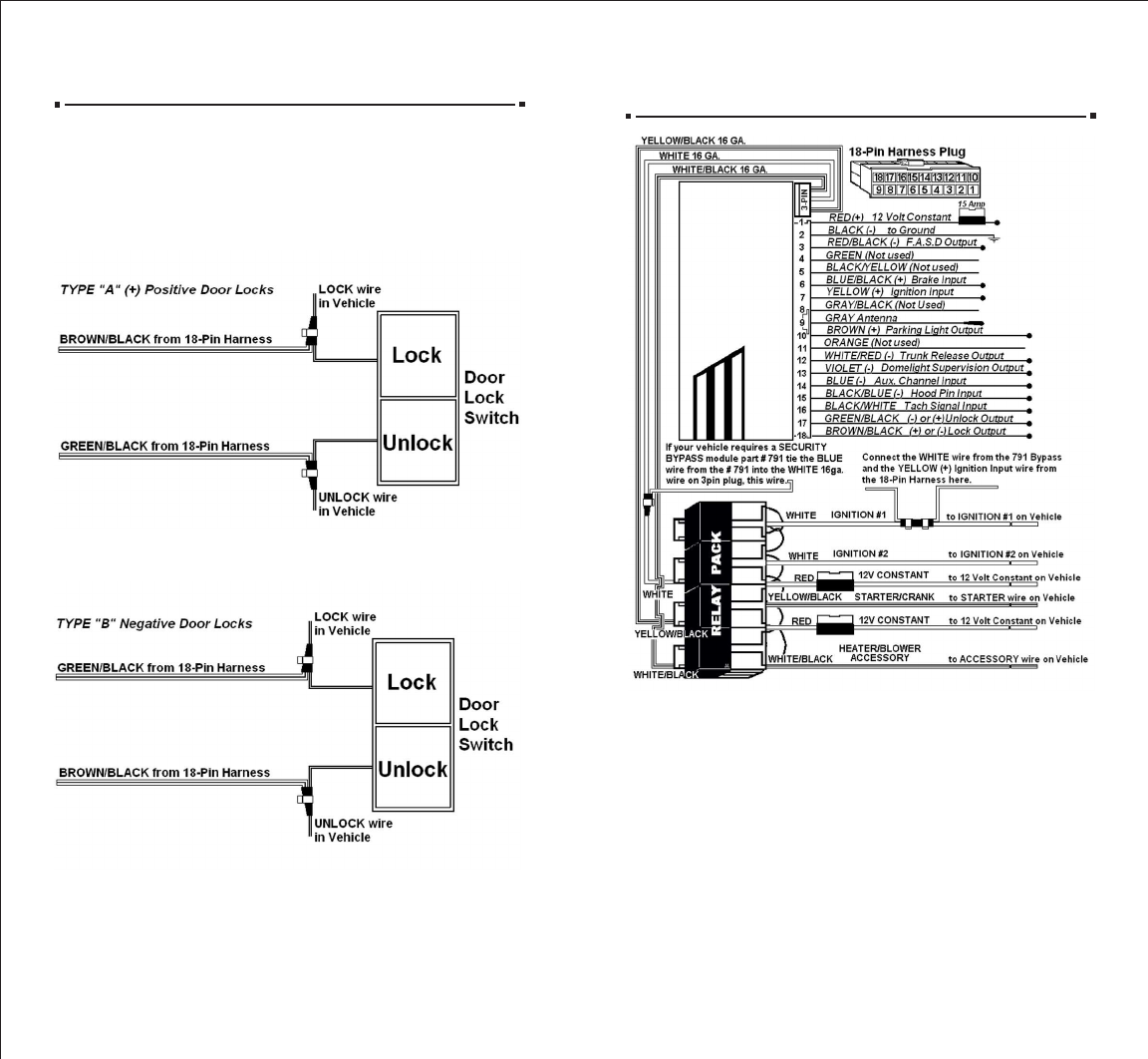
CONNECTING “TYPE B LOCKS”
• If your vehicle has a “Type B” door locking system, connect
the GREEN WITH BLACK STRIPE wire from the 18-pin harness to
the door lock wire. Connect the BROWN WITH BLACK STRIPE wire
to the unlock wire. See diagram below.
CONNECTING “TYPE C LOCKS”
•If your vehicle has a “Type C” door locking system, you
will need to purchase optional part #778. Once you have
purchased the relays, follow the diagram on page 17 for
“Type C” door locks.
CONNECTING DOOR LOCKS (Optional)
CONNECTING “TYPE A LOCKS”
•If your vehicle has a “Type A” door locking system, connect
the BROWN WITH BLACK STRIPE wire from the 18-pin harness
to the door lock wire. Connect the GREEN WITH BLACK STRIPE
wire to the unlock wire. See diagram below.
IMPORTANT NOTICE: This unit when first powered up must be initialized
to code in the Remote Control.
INITIALIZATION OF THE CONTROL MODULE.
When the unit is first powered up and all the connections are completed
with the harness plugged into the control module, the Parking Lights on
the vehicle will begin to flash.
You must make sure the Hood is opened (if the Hood Pin Switch is connected)
if not, connect the Hood Pin Switch wire to a good Body Ground, then press
and hold the Brake Pedal. With the brake pedal held, press and release
the START Button on the Remote Control, the Parking Lights will then stop
flashing. Release the brake pedal on the vehicle and close the hood or
remove the Hood Pin Switch wire from ground.
This procedure must be used if the Remote Control is lost (learning a
replacement Remote Control) or the unit’s memory is cleared.


