


axxessinterface.com 800.221.0932
3
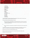
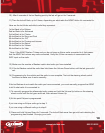
USB PORT COVER PROGRAMMING LED
RESET BUTTON
PIN
1
PIN
2
PIN
3
PIN
4
PIN
5
PIN
6
PIN
12
PIN
11
PIN
10
PIN
9
PIN
8
PIN
7
A brief overview of the ASWC interface and wire harness:
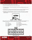
On the top of the ASWC interface there are three points of interest:
1) The Programming led – this will ash rapidly when in auto detect mode, ashes slowly in manual
programming mode
2) The Reset button – Hold down button more then 2 seconds but less then 10 seconds to start auto
detect mode; hold down longer then 10 seconds to start manual programming mode
3) The slide cover for the USB update port – open this up to reveal the USB update port. Using the
USB-CAB update cable and the Axxess website you can make sure you always have the latest,
updated inventory.
Below are the wire colors of the ASWC. Please go to the Axxess website (www.axxessinterface.com)
for detailed information on your speci c vehicle and what color wire(s) to use on the ASWC.
Pin 1 – Pink
Pin 2 – White/Green
Pin 3 – Orange/Green
Pin 4 – Green/Orange
Pin 5 – Gray/Red
Pin 6 – Black
Pin 7 – Blue/Pink
Pin 8 – Black/Green
Pin 9 – Red (Tip of 3.5mm connector)
Pin 10 – White (Ring of 3.5mm connector)
Pin 11 – Gray/Blue
Pin 12 – Red
Wire Insertion View