UNLOCK RELAY
Orange = N.O. Relay Contact
Dark Blue = N.C. Relay Contact
White = Common Relay Contact
LOCK RELAY
Blue/White Tracer = N.O. Relay Contact
Dark Green = N.C. Relay Contact
Yellow = Common Relay Contact
GREY & BLACK 2 PIN (blue) CONNECTOR: VALET SWITCH
Route thetwo conductor,blue connectorfrom thevalet switchto thealarm controlmodule, andplug itinto themating blueconnector
on the side of the module.
RED & BLUE WIRES: DASH MOUNTED L.E.D.
Routethetwoconductor,whiteconnector (redand bluewires)from theL.E.D. tothe alarmcontrolmodule, andplug itinto themating
white connector on the side of the module.
6 PIN DOOR LOCK OUTPUT CONNECTOR: NORMAL OPERATION
The orange, blue w/white tracer, yellow, white, green, and blue wires in the 6 conductor connector are the contacts of the on- board
door lock relays. The function of each of these wires is listed below;
3 WIRE GROUND SWITCHED DOOR LOCK CIRCUITS:
In these vehicles, the dark green and dark blue door lock wires are not used.
The orange and blue w/white stripe wires must be connected to a chassis ground source.
The yellow wire is the ground pulse "lock" output, and should be connected to the negative lock relay control wire in the vehicle.
The whitewire isthe groundpulse "unlock"output, andshould beconnected tothe negativeunlock relay controlwire inthe vehicle.
3 WIRE POSITIVE SWITCHED DOOR LOCK CIRCUITS:
In these vehicles, the dark green and dark blue door lock wires are not used.
The orange and blue w/white stripe wires must be connected to a +12 volt battery source.
The yellow wire is the positive pulse "lock" output, and should be connected to the positive lock relay control wire in the vehicle.
The white wire is the positive pulse "unlock" output, and should be connected to the positive unlock relay control wire in the
vehicle.
5 WIRE ALTERNATING DOOR LOCK CIRCUITS:
In this application, it is necessary to cut the existing door lock by-pass wires. These wires run from the master door lock switch to
the slave door lock switch, and then on to the door lock motors.
Cut the existing lock wire, and connect the yellow wire to the slave switch or motor side of the cut wire. Connect the green wire to
the master switch side of the cut wire.
Cut the existing unlock wire, and connect the white wire to the slave switch or motor side of the cut wire. Connect the blue wire to
the master switch side of the cut wire.
The orange and blue w/white stripe wires must be connected to a fused +12 VDC battery source.
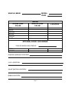
Refer to the AUDIOVOX Door Lock Wiring Supplement for proper connection of these wires into the various locking circuits
available in current vehicles.
Page 5
Whenusingthis channelforanaccessoryotherthan trunkrelease,connectonedark bluewire totheaccessory,andthe otherdarkblue
wire to either chassis ground, or, to a fused + 12 volt battery source, depending upon the requirements of the accessory.
WARNING: Neverattempt topull morethan 10Amperes ofcurrent throughthis relay.The circuitwill be damaged.Always
check the requirements of accessories prior to connecting them to the circuit.
2 DARK BLUE WIRES: PULSED OUTPUT / CHANNEL 2 (TRUNK RELEASE)
The dark blue wires are controlled via an independent RF channel from the keychain transmitter. These are the NO and COMMON
contacts of an on board, 10 A relay, so they can be connected to positive or negative switched circuits.
Connect one ofthe dark blue wiresto the output ofthe trunk release push-buttonswitch, and the otherdark blue wire toeither chassis
ground, or + 12 VDC battery, depending on the polarity of the trunk release circuit in the vehicle.


