


LED Flash Pattern
1 Flash Pause etc.
2 Falsh Pause etc.
3 Flash Pause etc.
4 Flash Pause etc.
5 Flash Pause etc.
6 Flash Pause ect.
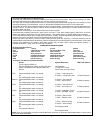
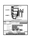
ALARM SELECTABLE FEATURES
RF Programmable Features:
Feature Selection 1 Chirp 2 Chirp Default
First 1 Second Door Locks 3.5 Second Door Lock 1 Second
Second Auto Lock On Auto Lock Off Auto Lock Off
Third Auto Unlock On Auto Unlock Off Auto Unlock Off
Fourth Headlight Output On Headlight Output Off Headlights On
Fifth Passive Door Locks Active Door Locks Active Door Locks
Sixth Passive Arming Active Arming Passive Arming
To Program The Alarm's Selectable Features:
First
Second
Third
Fourth
Fifh
Sixth
Action
Turn the ignition switch on
Flip the valet/program switch on then off 3 times
Within 3 seconds, turn the ignition switch off,
then on
Press transmitter button 1 to change.
Or
Flip valet/program switch on then off
Press transmitter button 1 to change.
Or
Flip valet/program switch on then off
Press transmitter button 1 to change.
Or
Flip valet/program switch on then off
Press transmitter button 1 to change.
Or
Flip valet/program switch on then off
Press transmitter button 1 to change.
Or
Flip valet/program switch on then off
Press transmitter button 1 to change.
Or
Flip valet/program switch on then off
Or
Turn ignition switch off.
System Response
No Response
1 Chirp-LED 1 Flash
Short Chirp, then Long Chirp
1 Chirp = 1 second Locks
2 Chirps = 3.5 second Locks
2 Chirps = auto locks off
1 Chirp = auto locks on
2 Chirps = auto unlock off
1 Chirp = auto unlock on
1 Chirps = headlight o/p On
2 Chirp = headlight o/p Off
2 Chirps = Active Locks
1 Chirp = Passive Locks
1 Chirp = passive arming
2 Chirps = active arming
Exit Program Mode
Exit Program Mode
NOTE: Once you've entered the program mode DO NOT allow more than 15 seconds to pass between steps, or the program-
ming mode will be terminated.
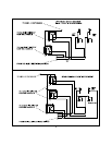
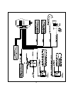
Connecting And Adjusting The Shock Sensor:
Route the 4 pin cable from the previously installed shock sensor to the control module. Plug it into the mating 4 pin white
connector shell located along side the 8 pin main harness connector of the control unit.
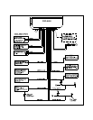
Pre- adjust the previously installed Shock Sensor by first accessing the potentiometer setting screw and carefully turn this
adjustment all the way counterclockwise. Now Turn the adjuster clockwise to the first notch on the module case.
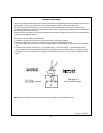
CAUTION! Use caution when striking the vehicle and around the glass panels. Impact tolerances of vehicle glass differs from
vehicle to vehicle. This test can also be made by striking the vehicle bumpers providing you consider the amount of force
required to break a window.
Exit the vehicle, close all doors, hood and trunk and arm the alarm system.
Firmly strike the windshield pillar with the open palm of your hand. If the alarm system triggers, disarm then re-arm the
system and make the same test on the rear window support. If the system triggers, no further adjustment is necessary.
If in the above test the sensor did not trigger the alarm system, carefully move the adjustment potentiometer in a clockwise
direction and re-test in the same manner until the desired results are achieved.
Confirm the Alarm's operation by arming the alarm, testing an entry point then disarming. Follow this sequence until all
protected areas have been tested. While testing, observe the operation of the parking lights for proper operation, confirm that
the siren chirp patterns for arm, disarm, disarm after intrusion and arm while a door is open are operating properly. If
headlight illumination is used, check to insure proper operation.
7