


Dark Green Wire: (-) Instant Trigger Zone 2
The Dark Green wire is the instant on ground trigger input wire. This wire must be connected to the hood and trunk pin
switches previously installed. Note: This wire will be shunted when remote control channel 2 is accessed, (trunk release).
This wire will remain shunted all the while there is ground present, and for 5 seconds after the ground is removed. This allows
the operator to open the trunk via the remote transmitter without having to first disarm the alarm system.
Brown Wire: (-) Negative Door Trigger Input
If the vehicle's door courtesy light switches ground when the door is opened, (Most GMs and Imports), you must connect this
wire to the negative output from one of the vehicle's door pin switches. In most cases the Brown wire will need to be connected
to only one door switch no matter how many doors the vehicle has as most door lighting circuits are wired in parallel.
Purple Wire: (+) Positive Door Trigger Input
If the vehicle's door courtesy light switches + 12 volts when the door is opened, (Most Fords and some Imports), you must
connect this wire to the positive output from one of the vehicle's door pin switches. In most cases, the Purple wire will need to
be connected to only one door switch no matter how many doors the vehicle has as most door lighting circuits are wired in
parallel.
Yellow Wire: (+) 12 Volts Ignition Switch Input
Connect this wire to a source in the vehicle that is live when the ignition switch is in the on and start positions, and has 0 volts
in all other switch positions.
White w/ Blue Trace Wire: Low Current (-) Ground Headlight Output
The White w/ Blue Trace wire is provided to operate the optional headlamp illumination feature of the system. This is a low
current (300mA) output and must be connected to an external relay to control the high current switching circuit of the vehicle's
headlamps. To use this option, Connect the White /w Blue Trace wire to terminal # 86 of a P&B VF45F11 relay or equivalent.
Connect Terminals #85 and # 30 to a fused + 12 Volts source with a current capability equal to or in excess of the factory
headlamp fuse. Connect terminal # 87 of the relay to the switched + 12 volt wire feeding the vehicle's headlamp circuit.
NOTE: For ground switched headlamp circuits, Connect the White /w Blue Trace wire to terminal # 86 of a P&B VF45F11
relay or equivalent. Connect Terminal #85 to a fused + 12 Volts source. Connect terminal # 30 to a clean chassis ground.
Connect terminal # 87 to the ground switched headlamp control wire in the vehicle.
Light Green Wire: (-) Instant Trigger Zone 1
This is a instant on ground trigger input intended for the connection of optional triggering devices. The ground trigger output
wire of motion detectors, microwave detectors, or glass break detectors, can be connected to this Light Green trigger input
wire.
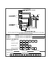
2 Pin Valet/Program Switch: (Blue Connector)
The Black & Grey twin lead wires loaded in the two pin blue connector are the ground supply and program/valet input of the
PRO-9600. When the Grey wire is grounded, under certain conditions, the unit will enter the valet mode. When the Grey wire
is sequentially grounded under other conditions, the unit will enter the various program modes. Route the twin lead Black and
Grey wires from the valet/Program switch to the PRO-9600 and plug the two pin connector into the mating blue connector shell
of the control module. Refer to the remote programming, feature programming and function programming shown later in this
installation guide for operation of the valet/program switch.
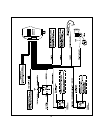
2 Pin Door Lock/Unlock Harness: (White Connector)
The Red & Green Door Lock/Unlock output wires provideeither a pulsed ground or pulsed + 12 volts to control the vehicle door
lock / unlock circuits. The output of these wires has a maximum switching capability of 300mA. Many vehicles today have
factory door lock relays which can be connected directly to these outputs, however always confirm that the factory relays in
your particular vehicle do not exceed the rated 300mA output of the unit's door lock/unlock circuit. Plug the two pin connector
of the door lock/unlock harness into the mating connector shell of the control module. Determine the door lock circuit of the
vehicle you are working on and wire according to the diagrams shown.
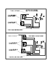
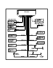
3 Wire Ground Switched Door Lock Circuits:
In this application, the Red wire of the two pin harness provides a ground pulse during the arming sequence, or pulsed ground
lock output. Connect the Red wire to the low current ground signal from the factory door lock switch to the factory door lock
relay.
The Green wire of the two pin harness provides a ground pulse during the disarming sequence, or pulsed ground unlock
output. Connect the Green wire to the low current ground signal from the factory door unlock switch to the factory door unlock
relay.
3 Wire Positive Switched Door Locks:
In this application, the Red wire of the two pin harness providesa+12volt pulse during the disarming sequence, or pulsed
12 volt unlock output. Connect the Red wire to the low current 12 volt signal from the factory door unlock switch to the factory
door unlock relay.
The Green wire of the two pin harness providesa+12volt pulse during the arming sequence, or pulsed 12 volts lock output.
Connect the Green wire to the low current 12 volt signal from the factory door lock switch to the factory door lock relay.
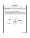
Note: For connection to Four Wire Polarity Reversal, 5 Wire Alternating 12 Volts, And All Other Door Lock Circuits the
Audiovox AS-9159 Door Lock Interface, (or equivalent 30 A automotive Relay must be used. Refer to the Audiovox Door Lock
Wiring Supplement for proper wiring of these circuits.
5