


VSS WIRING SUPPLEMENT
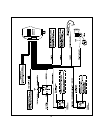
The two pin auxiliary harness with the red connector shell provides a input signal to the control module from the vehicle's
Speed Sensor ( VSS), and provides a low current ground switched output to control a shut down relay.
The relay can be used to interrupt any circuit in the vehicle which will cause the vehicle's engine to stop running.
Typically the contacts of this relay can be used to interrupt the primary (+) feed wire of the ignition coil or the positive feed
wire controlling the electric fuel pump.
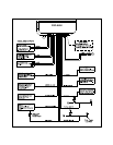
Whichever circuit you choose to interrupt, be certain that you fully test the operation of the shut down circuit as described
on page 6 of the installation manual.
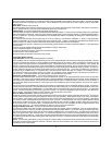
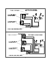
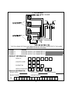
TO INSTALL THE VSS SHUT DOWN CIRCUIT:
1. Locate the VSS signal wire found in the vehicle at the ECM or the signal generator.
2. Connect the Black wire of the two pin connector to the previously located VSS signal wire.
3. Connect the Red wire of the two pin connector to terminal #86 of a P&B VF45F11 or equivalent 12 volt automotive
relay.
4. Connect terminal # 85 of the relay toa+12volt ignition source. This wire will have + 12 volts with the ignition
switch turned to the on and start positions and will have 0 volts with the ignition switch in the off or accessory positions.
5. Connect the common contact (#30), and normally closed contact (87a) to the circuit you wish to interrupt as shown
below.
NOTE: Be certain to follow the test procedure as outlined on page 6 of the installation manual.
12
Form No. 128-5167
Red Wire Of 2
Pin VSS Harness