


White w/ Black Trace Wire: Positive (+) Siren Output
This is the positive siren feed wire. Route this wire through a grommet in the firewall to the siren location. Connect the White
w/ Black Trace wire to the Red wire of the Siren. Secure the Black wire of the Siren to a known chassis ground or solid clean
metal surface.
Black Wire: Chassis Ground Source
Connect the Black wire to a known vehicle ground source or to a solid clean metal part of the chassis. Be certain to remove any
paint or grease and secure this wire with a self taping screw and ring terminal.
2 White Wires: Low Current Directional Light Flash Output Wires
The PRO-9600 provides two different and distinguishable light flash patterns. During normal arming and disarming, a standard
alarm flash pattern is observed. When the unit is placed in a theft mode, from the paging network, a special light flash pattern,
(S.O.S.) is observed. This highly recognizable and very different flash pattern is necessary to distinguish a vehicle theft from a
vehicle break-in.
You must consider that the parking lights may be in the on position if the vehicle is carjacked or stolen, In this application
special consideration for wiring of the light flash circuit must be made. Audiovox advises that the directional element of the
bulbs be used in all cases to insure that this light flash pattern will be operational in all situations.
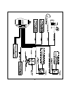
The two White wires provide, ( 300mA) low current pulsed ground outputs to control the light flash patterns. In all cases relays
must be used.
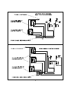
Three of the most common directional circuits available in today's vehicles are:
1. Four Independent Bulbs, LF,LR,RF,RR.
2. Left Front And Rear Common / Right Front And Rear Common
3. Rear Common Front Independent.
Wiring for these circuits are shown later in this manual.
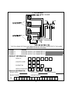
10 Pin Mini Wiring Harness:
Light Blue Wire: Low Current Latching Output / Channel 4
The Light Blue, channel 4 output wire latches to ground via an independent RF channel from the keychain transmitter. Channel
4 is also considered the Auxiliary 3 output available by satellite paging to the vehicle. When operating this channel from the
paging network, this output will be a pulsed 800ms output. Consider this when connecting to an accessory in the vehicle. Be
certain to list the function of this output in the Owners Manual, Owners Paging Manual, and on the rear page of this manual.
This wire provides an immediate ground signal, and remains grounded as long as the transmitter button(s) is held. This is a low
current (300mA) output and in all cases will be used to drive an external relay coil. To use the Light Blue wire, connect it to
terminal # 86 of a P&BVF45F11 or equivalent relay. Connect terminal # 85 of the relay to a fused + 12 volt battery source.
Connect terminal # 30 of the relay to ground or a fused + 12 volt battery source, dependent upon the device in the vehicle you
wish to control. Connect terminal # 87 to the vehicle's switched device's control wire.
Dark Green w/ Black Trace Wire: low Current Latching Output / Channel 3
The Dark Green w/ Black trace, channel 3 output wire latches to ground via an independent RF channel from the keychain
transmitter. Channel 3 is also considered theAuxiliary 2 output available by satellite paging to the vehicle. When operating this
channel from the paging network, this output will be a pulsed 800ms output. Consider this when connecting to an accessory in
the vehicle. Be certain to list the function of this output in the Owners Manual, Owners Paging Manual, and on the rear page of
this manual.
This wire provides an immediate ground signal, and remains grounded as long as the transmitter button(s) is held. This is a low
current (300mA) output and in all cases will be used to drive an external relay coil. To use the Dark Green w/ Black Trace wire,
connect it to terminal # 86 of a P&BVF45F11 or equivalent relay. Connect terminal # 85 of the relay to a fused + 12 volt battery
source. Connect terminal # 30 of the relay to ground or a fused + 12 volt source, dependent upon the device in the vehicle you
wish to control. Connect terminal # 87 to the vehicle's switched device's control wire.
Black w/ White Trace Wire: 300mA Ground Horn Output
The Black w/ White Trace wire will provide a pulsed ground output which can be used to sound the vehicle's horn. This is a low
current (300mA) output and must be connected to a relay for proper operation. Most vehicles have a horn relay connected to
the horn switch. If the existing relay requires less than 300 mA then direct connection to the horn wire is possible. If the vehicle
horn does not switch a existing low current relay or if the horn circuit is + 12 volts switched, you must connect the Black w/ White
Trace wire to a external relay coil. When connecting to an external relay, connect the Black w/ White Trace wire to terminal #
86 of a P&B VF45F11 or equivalent relay. Connect terminal # 85 to a fused +12 volt battery source. Arrange terminals # 30 &
# 87 to switch ground or + 12 volts as necessary for the horn circuit you are connecting to.
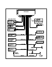
Orange w/ White Trace Wire: Low Current Ground When Disarmed Output
The Orange w/ White Trace wire provides a ground output when the security system is disarmed. This low current (300mA),
output may be used to control a normally open Starter Inhibit Circuit where desired. To use the Orange w/ White Trace wire,
Connect the Orange w/ White Trace wire to terminal # 86 of a P&BVF45F11 or equivalent relay. Connect terminal # 85 of the
relay to an ignition wire in the vehicle that has + 12 volts when the ignition key is in the on and start positions and has 0 volts in
the off and accessory positions. Locate and cut the low current start solenoid wire found at the vehicles ignition switch harness.
Connect terminal # 30 of the relay to the ignition switch side of the cut wire. Connect terminal # 87 of the relay to the starter side
of the cut wire.
NOTE: This normally open starter cut relay arrangement will prevent the vehicle from starting if the control module or wiring to
the control module is disconnected or removed. Audiovox does not recommend the use of this circuit to interrupt anything but
the starting circuit of the vehicle.
4