


The PRO-9600 is a full featured security system with on board paging technology that provides the consumer a direct link
to their vehicle from anywhere in the world. This patent pending technology allows the user to operate the vehicle from any
land or mobile telephone. The vehicle's owner can command the security system to arm or disarm, release the trunk, start
the vehicle, and in case of a carjacking, can put the PRO-9600 in a special carjack mode that will flash the lights, sound the
siren and prevent restarting of the vehicle.
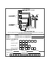
NOTE: Many of the paging features available to the consumer are part of the alarm functions of the unit. Features such as
lock / unlock, arm, disarm, carjack, and reset will be available after installation with no special consideration on the part of
the installing technician. There are three additional auxiliary outputs accessible by paging the PRO-9600 that will require
some consideration. The Alarm's receiver channels 2, 3, and 4, are the same as paging auxiliary functions 1, 2, and 3.
These outputs, when connected to the vehicle, MUST BE NOTED on the Owners Guide, Rear Page Of This Manual and on
the Paging Registration Guide. Additionally, access from the RF transmitter may provide a latched output from these
channels however access from the paging network will only provide a 800 ms pulsed output. Please note this as it may
effect the options that you connect to these output wires. Each wire is referenced individually later in this manual.
MOUNTING THE COMPONENTS:
CONTROL MODULE:
Select a mounting location inside the passenger compartment up and behind the dashboard. The mounting location
selected must consider routing of the antenna to allow it to be fully extended, away from metal which may shield it, and as
high as possible to insure the best RF reception and operating range. Additional consideration should be made to keep the
control module away from on-board computers. These devices have local oscillators which may produce RF and inhibit or
limit reception.
Be certain that the chosen location will not interfere with proper operation of the vehicle. Avoid mounting the module to or
routing the wiring around the steering shaft/column, as the module's wiring may wrap around or block the steering wheel
preventing proper control of the vehicle. Secure the module in the chosen location using cable ties or screws as necessary.
Do Not Mount The Module In The Engine Compartment, it is not waterproof.
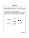
SIREN:
Select a location in the engine compartment that is not accessible from below the vehicle. The selected location must be
clear of hot or moving parts within the engine compartment. The siren must be pointed downward to prevent water retention
and the flared end must be pointed away and out of the engine compartment for maximum sound distribution. Before
securing the siren, check behind your chosen location to assure that the mounting screws will not penetrate any factory
wiring or fluid lines. Secure the siren mounting bracket using #8 self taping screws or, by first using the mounting bracket as
a template, scribe or mark the three bracket mounting holes. Drill the three marked holes using a 1/8" drill bit, then mount
the siren using #8 sheet metal screws.
HOOD AND TRUNK PIN SWITCHES:
The pin switches included in this package are intended for protecting the hood and trunk areas of the vehicle. In all cases,
the switch must be mounted to a grounded metal surface. When the pin switch is activated, (hood/trunk open), it will supply
a ground to the input wire activating the alarm. Mount the switches under the hood and in the trunk compartment in
locations away from water drain paths. If necessary, the included brackets may be used to move the switch away from rain
gutters or allow mounting to the firewall behind the hood seal. In both cases the switch must be set up to allow the hood or
trunk to depress the switch at least 1/4 inch when the hood or trunk is closed and fully extended when the hood or trunk is
opened. For direct mounting, a 1/4 inch hole must be drilled. Carefully check behind the chosen location to insure the drill
will not penetrate any existing factory wiring or fluid lines. Drill a 1/4" hole in the desired location and thread the pin switch
into it using a 7/16" nut driver or deep well socket. If using the mounting bracket, first secure the bracket to the desired
location and secure the pin switch in the pre-threaded mounting bracket hole.
DASH MOUNTED L.E.D:
The small red LED included in the kit will serve as a visual indicator of the alarm's status and provide a visual deterrent to
a potential thief. The LED also provides important feed back information during the transmitter andfeature program modes.
The LED should be installed in the dash in an area highly visible so that it may be seen from the driver's seat as well as from
outside the vehicle. Inspect behind the chosen location to insure that the drill will not penetrate any existing factory wiring
or fluid lines. Carefully drill a 1/4" hole in the desired location and pass the connector end of the LED through the hole and
toward the control module. Press the LED firmly into place until it is fully seated in the mounting hole.
2