


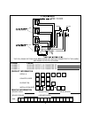

VALET/PROGRAM SWITCH:
Select a mounting location that is easily accessible to the operator of the vehicle. The switch can be mounted to the lower
dash panel in the driver's area. Inspect behind the chosen location to insure that adequate clearance is allowed for the
body of the switch, as well that the drill will not penetrate any existing factory wiring or fluid lines. Drill a 1/4" hole in the
desired location and mount the switch by passing it through the panel from the underside. Secure the switch using the nut,
star washer, and on/off face plate. It is suggested that the switch be oriented to allow the on position to be up toward the
driver and the off position to be down or away from the driver. Route the switches's connector toward the control module.
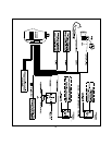
SHOCK SENSOR:
Select a centrally located, solid mounting surface for the shock sensor that will allow consistent operation from all areas of
the vehicle. The selected location must be within 18" of the control module to allow routing and connecting of the 4 pin
harness. Secure the shock sensor to the chosen location using two #8 self taping sheet metal screws. The sensor can
also be secured to an existing dash brace using cable tie straps. Whichever mounting method is used, be sure to allow
access to the sensitivity adjustment potentiometer for use later in the installation.
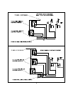
STARTER INHIBIT RELAY:
Select a mounting location within 12" of the ignition switches low current start solenoid wire. Secure the relay to an existing
harness in the chosen location using a cable tie around the relay's wiring harness. Caution! Do not wire tie the metal
bracket to an existing wiring harness as vibration may cause chaffing and shorting damaging the factory wiring. If an
existing harness is not available then secure the relay's metal mounting tab to an under dash metal brace with a #8 self
taping sheet metal screw. Wire the relay as per the diagram found later in this manual.
NOTE: Before connecting the module, pre-select all the wires in the vehicle. First, using a digital VOM, test all the wires
you intend to connect to in the vehicle. Disconnect the vehicle battery and complete all wiring to the vehicle before
connecting the control module to the harness connectors. This will prevent the pager from activating during the installa-
tion. Once all wiring is complete and the module is connected, disarm the unit immediately before proceeding with the
testing of the unit.
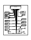
WIRING THE CONTROL MODULE:
8 Pin Main Wiring Harness
Red w/White Trace: + 12 volts Battery Source
Connect this wire to a constant + 12 VDC source found at the vehicles ignition switch using the 5 Amp fuse and holder
provided.
Orange Wire: Ground When Armed Output
This wire provides a 300 mA ground output when the alarm circuit is armed to control the starter inhibit relay. Connect the
Orange wire to terminal #86 (orange wire) of the previously installed starter interrupt relay. Connect terminal #85 (red wire)
of the relay to an ignition wire in the vehicle that is live when the ignition switch is turned to the on and start positions and
off when the key is off. Locate and cut the low current start solenoid wire found at the vehicles ignition switch harness. This
wire will have + 12 volts when the ignition key is moved to the start (crank) position and will have 0 volts in all other key
positions. Connect one side of the cut wire to terminal #87a ( Black wire) of the relay. Connectthe other side of the cut wire
to terminal #30 (White/Black wire) of the relay.
Green w/ White trace Wire: Entry Illumination Ground Output
This wire provides a 30 second ground output (300 mA Max.) whenever the remote is used to disarm the alarm or to unlock
the doors and provides a continuous pulsed output whenever the alarm is triggered. This wire should be connected to an
external relay and wired to the vehicles interior entry lighting whenever the optional Interior Illumination circuit is desired.
Dark Blue Wire: Delayed 300mA Pulsed Channel 2 Output
The Dark Blue channel 2 output wire supplies a 300mA ground pulsed output whenever channel two of the receiver is
accessed. Pressing the pre-programmed transmitter button for three seconds will access channel two. Channel 2 is also
considered auxiliary output 1 available by satellite paging to the vehicle. Whether accessing this output form the key chain
transmitter or via the satellite paging network, the Dark Blue wire will provide a 800ms pulsed ground output. This is a low
current output and must be connected to a relay to supply power to the trunk release or the circuit you wish to control.
Connect the Dark Blue wire to terminal # 86 of a VF45F11 P&B relay or equivalent. Connect terminal # 85 of the relay to
a fused + 12 volt battery source. Connect the common, normally open, and normally closed contacts of the relay to
perform the selected function of channel 2.
3