


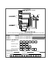

2 Pin Auxiliary Harness: (Red Connector)
The two pin auxiliary connector is used to control vehicle shut down from a paging theft command. See supplement for wiring
information.
Connecting The Dash Mounted LED:
Plug the two pin white connector from the previously installed LED into the mating two pin white female connector shell of the
control module.
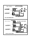
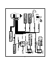
Connecting The PRO-9600 Module:
Re-connect the vehicle's battery then plug themain and mini connectors into the mating connector shells of the control module.
Immediately disarm the system with the hand-held transmitter to prevent the pager board from activating.
Programming The PRO-9600:
The transmitter programming is pre-set from the factory so that Button 1 controls Arm/Disarm, Button 2 controls Channel 2
output, Button 3 controls Channel 3 output, Button 2&3 controls Channel 4. If the consumer wishes a different configuration,
see separate transmitter programming guide packaged with this kit.
Keep in mind that Alarm Channel 2 = Pager Auxiliary output 1, Alarm Channel 3 = Pager Auxiliary output 2, and Alarm Channel
4 = Pager Auxiliary output 3.
The alarm features are pre-programmed at the factory for the most common configuration. If you wish to change any of these
settings, refer to the Alarm Selectable Feature programming later in this manual.
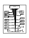
Testing The PRO-9600:
Testing The Unit's Outputs Via The On Board Test Switch:
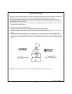
IMPORTANT! Do not fax the activation sheet until the system has been thoroughly tested, and all functions that have been
connected are operating properly.
Note: Make sure that you have at least 1 window open and the keys out of the vehicle before operating the test switch or the
paging test sequence.
1. Slide open the access door of the module case and locate the push button test switch.
2. Using the rubber end of a pencil eraser, depress the push button one time.
The PRO-9600 will simulate the following events sequencing through each command with a 5 second interval between each
sequence:
A. Auxiliary Output 1 C. Auxiliary Output 3 E. Arm Alarm G. Carjack
B. Auxiliary Output 2 D. Door Unlock F. Disarm Alarm H. Reset All
After the push button test is complete and you've confirmed the proper operation of all functions, proceed with the Radio
Frequency Test.
3. From a touch tone phone, dial the appropriate test phone number and request a test signal for the serial number of the unit
being tested.
4. The signal will be received at the vehicle and the following sequence of events will be observed. There will be a 5 second
interval between each sequence:
A. Auxiliary Output 1 C. Auxiliary Output 3 E. Arm Alarm G. Carjack
B. Auxiliary Output 2 D. Door Unlock F. Disarm Alarm H. Reset All
After confirming that all options connected to the PRO-9600 are operating properly, complete the activation form supplied
with the unit. Make sure all selectable auxiliary options are clearly identified on the application sheet, owners manual and on
the last page of this manual.
NOTE: After verifying that the RF test was successful, you will need to specifically test the theft / hijack command for two
functions.
1. During this portion of the test,the vehicle must be running. From a touch tone phone, dial the appropriate test phone number
and request a theft signal for the serial number of the unit being tested. Once the signal is received, turn the engine off.
Attempt to restart the vehicle. If the engine starts, check your connections to the starter inhibit relay. After verifying that the
engine will not start after receiving the RF theft command, reset the system by calling the test telephone number and request
a reset command for the unit being tested.
2. During this portion of the test, be sure that the vehicle is started and moving. You must confirm that the vehicle will not shut
down until 5 seconds after the vehicle comes to a complete stop. This will confirm that the VSS connection and ignition
interrupt circuits are operating properly. Failure to complete this portion of the test could result injury to the occupant(s) of
the vehicle. This test may require the use of an assistant to place the call if you do not have a cellular phone available.
While driving above 3 MPH, call the test telephone number and request a theft/hijack signal be sent. Once the signal has
been received, wait 10 seconds, then allow the vehicle to come to a complete stop. After 5 seconds, the vehicle should stall.
If the vehicle continues to run, you will need to recheck your connections to the ignition control relay. First call the test center
and request a reset, confirm your connectionsto the VSS circuit and the ignition control relay, then repeat the above test until
the vehicle stalls as described. Upon completion call the test center and request a reset.
6