


5
128-5560A
5 of 8
providing a ground pulse during the disarming sequence.
Connect the Red wire to the low current ground factory door "Lock" signal wire leading from the factory switch to the
factory door lock relay. Connect the Green wire to the low current ground factory door "Unlock" signal wire leading
from the factory switch to the factory door unlock relay.
WIRING FOR "POSITIVE PULSE" DOOR LOCK CIRCUITS:
This is a system commonly used on many domestic vehicle's factory door lock/unlock systems, particularly General
Motors and Chrysler, although not on all models. (Please see the note regarding "5-Wire Reverse Polarity Door
Lock Systems"). In this application, the Green wire serves as the "Lock" output, providing a positive pulse during the
arming sequence, and the Red wire serves as the "Unlock" output, providing a positive pulse during the disarming
sequence.
Connect the Green wire to the low current positive (+12VDC) factory door "Lock" signal wire leading from the factory
switch to the factory door lock relay. Connect the Red wire to the low current positive (+12VDC) factory door
"Unlock" signal wire leading from the factory switch to the factory door unlock relay.
4 WIRE POLARITY REVERSAL and 5 WIRE ALTERNATING DOOR LOCK CONTROL CIRCUITS:
In these applications, the AS-9159 Door Lock Interface (or equivalent 30 Amp. automotive type relays) must be used.
Refer to the Audiovox Door Lock Wiring Supplement for proper connection to these types of circuits.
PLUG-IN CONNECTIONS AND COMPLETING THE INSTALLATION:
Now that all the other components have been installed, and most of the main connections completed, it is time to
finish connecting the remaining plug-in components and completing the installation. Even though these are plug-in
connections, and the plugs have been shaped such that they cannot be plugged in wrong, please read and follow
the instructions below for each connection to make certain each component is properly installed.
DASH MOUNTED LED
2-PIN White Plug w/2 Wires; Red & Blue
The Red & Blue wires in the 2-PIN mini white connector control the anode and cathode of the dash mounted LED.
Route the twin lead Red and Blue wires from the LED to the control unit and plug the two pin connector into the
mating white mini connector shell of the control module. Do not force the connector, it will only plug in one way.
SHOCK SENSOR
Mounting The Shock Sensor
Never mount the sensor outside the vehicle where it will be exposed to the elements. Never mount any component
near hot or moving parts. Always mount the components and route the wiring away from the rotating steering shaft
assembly. Always mount the sensor within 22" of the alarm module to assure the plug in cable reaches the sensor.
1. Select a solid mounting location inside the vehicle. Ideally the inside firewall, center of the vehicle is best for
sensitivity. An alternate location can be the "A" pillar, "B" pillar, or suspended from an existing brace or wiring
harness.
2. Mount the sensor using the two screws provided or cable ties securing it to your chosen location.
Connecting The Sensor:
1. Connect the large 4 pin connector of the wiring harness to the 4 pin mating connector on the Shock Sensor.
2. Route the small 4 pin connector of the harness toward the alarm control module and connect to the mating 4 pin
connector on the alarm unit.
VALET/PROGRAM/MANUAL OVERRIDE SWITCH
2-PIN Blue Plug w/2 Wires; Black & Gray
The Black & Gray wires in the 2-PIN blue connector are the ground supply and Valet/Program input of the
APS-20LAD unit. When the Gray wire is grounded, under certain conditions, the unit will enter the valet mode.
When the Gray wire is sequentially grounded under other conditions, the unit will enter the various program modes.
Route the Black and Grey wires from the Valet/Program/Manual Override switch to the APS-20LAD unit and plug the
blue 2-PIN connector into the mating blue connector shell of the APS-20LAD control module. Do not force the
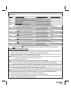
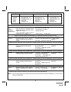
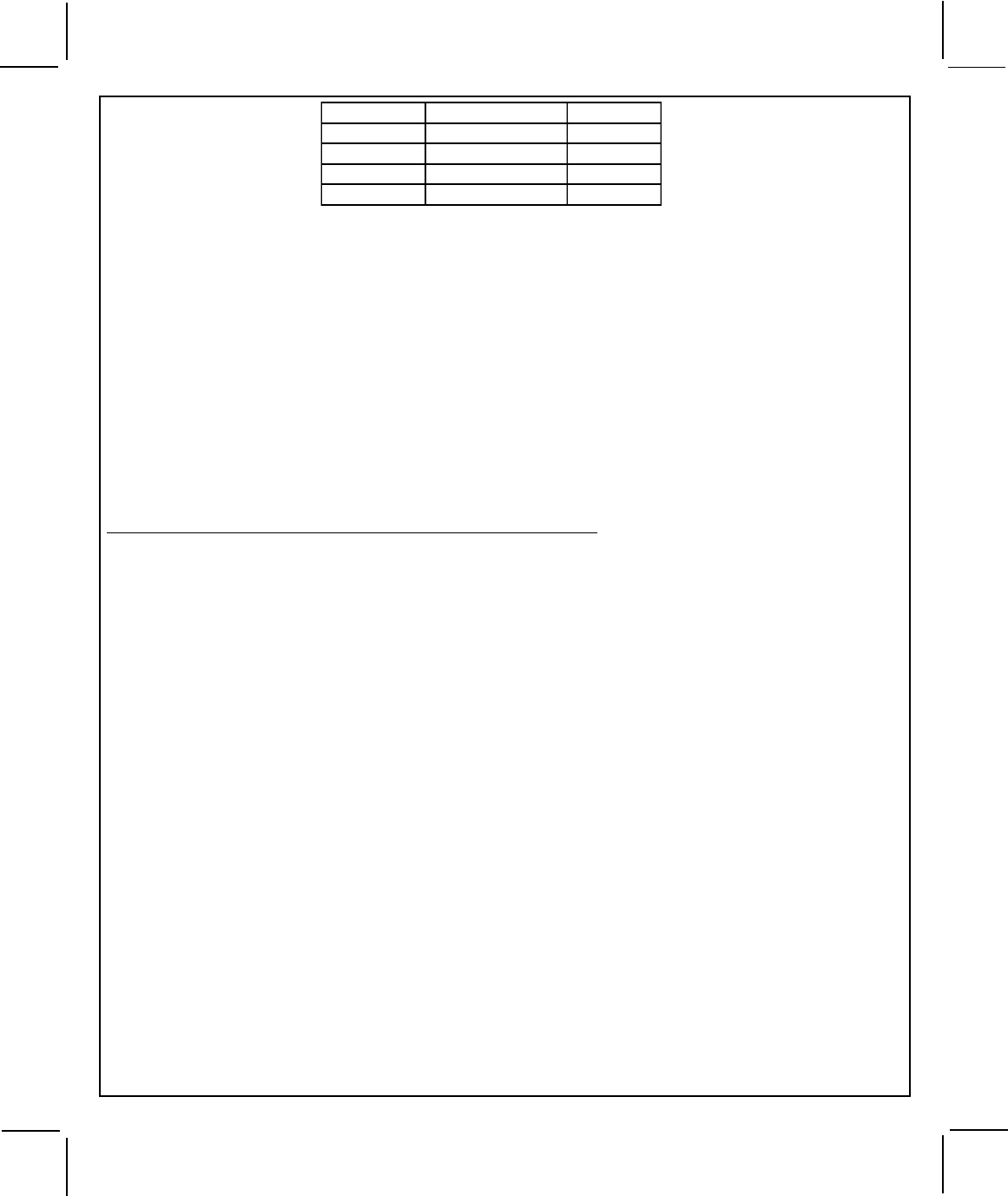
Wire Color Function Polarity
Red Lock Ground (-)
Red Unlock Positive (+)
Green Lock Positive (+)
Green Unlock Ground (-)