


3
128-5560A
3 of 8
extended when the hood or trunk is opened. For direct mounting, a 1/4 inch hole must be drilled. Carefully check
behind the chosen location to insure the drill will not penetrate any existing factory wiring or fluid lines. Drill a 1/4"
hole in the desired location and thread the pin switch into it using a 7/16" nut driver or deep well socket. If using the
mounting bracket, first secure the bracket to the desired location and secure the pin switch in the pre-threaded
mounting bracket hole.
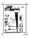
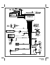
WIRING CONNECTIONS:
RED Wire (Connects to RED/WHITE wire at harness plug): Main Power Input Wire
These are the main power input wires for the APS-20LAD system. Both wires connect to a separate fuseholder
contained in the harness. These fuseholders each hold a separate ATC fuse, one 5AMP and one 15AMP. This RED
wire must be connected to a constant power wire at the vehicle's ignition switch harness or fusebox. Most vehicles
have at least one battery source wire supplying power to the ignition switch.
Locate a constant power wire or power taping point either at the vehicle's ignition switch harness or fuseblock. This
wire will read +12VDC at all times, regardless of the position of the ignition key switch. Splice and tape the RED
wire of the harness to this point.
YELLOW Wire: Ignition Input Wire
This wire provides the APS-20LAD system with an ignition power input from the vehicle. Connect this wire to the
primary ignition wire from the ignition switch. This vehicle wire will show +12VDC when the ignition key is turned to
the "ON" or "RUN" position
and
when turned to the "START" or CRANK" positions, and will have 0VDC when the
key is turned to the "OFF" and "ACCESSORY" positions.
Locate an ignition power wire at the vehicle's ignition switch harness. Splice and tape the YELLOW wire of the
system to this point.
WHITE Wire: Positive Parking Light Flash Wire
This wire is designed to provide a +12VDC positive light flash output, driven by the APS-20's internal relay, to be
connected directly to the vehicle's positive parking light circuit. Once the feedpoint is located, confirm that all the
vehicle's parking lights will illuminate when +12VDC is connected to it.
NOTE: Some vehicles, (mostly European) have isolated "left" and "right" side parking lights. To connect to
the parking light systems in these vehicles, you must use 2 separate SPDT or DPST relays to connect
one to each side in order to keep them isolated.
Locate a parking light feedpoint and attach the WHITE wire of the system to this point.
BROWN Wire: Negative (-) Door Trigger Input Wire
If the vehicle's interior lights are controlled by
grounding
door pin-switches (typical of most GM, Dodge, and import
vehicles), the Brown
negative
door trigger wire should connect to one of the vehicle's factory door pin switches. In
many cases the factory door pin-switches are wired in parallel, making it necessary to connect to only one door
switch in order to detect the opening of all doors. In a few cases this will not be true, making it necessary to connect
to the vehicle dome light, or isolate door trigger wires.
Locate the vehicle's negative door trigger wire in the vehicle's kick panel, under-dash or the vehicle's
pin-switch. Splice and tape the BROWN wire of the system to this point.
PURPLE Wire: Positive (+) Door Trigger Input Wire
If the vehicle's interior lights are controlled by
+12VDC
(Positive) door pin-switches (typical of most Ford vehicles),
the Purple
positive
door trigger wire should connect to one of the vehicle's factory door pin switches. In many cases
the factory door pin-switches are wired in parallel, making it necessary to connect to only one door switch in order
to detect the opening of all doors. In a few cases this will not be true, making it necessary to connect to the vehicle
dome light, or isolated door trigger wires.
Locate the vehicle's positive door trigger wire in the vehicle's kick panel or under-dash. Splice and tape the
PURPLE wire of the system to this point.
DARK GREEN Wire: Negative (-) Hood/Trunk Trigger Input Wire
This input is designed to connect to a
grounding
hood, trunk, or rear hatch pin-switch, to allow the system to trigger
should those entry points be violated. To provide protection for the hood, the Dark Green
negative
hood/trunk
trigger wire should connect to the existing factory hood pin-switch (if one exists) or to a suitable aftermarket in-
stalled hood pin-switch. To provide protection for the trunk or hatch, the Dark Green
negative
hood/trunk trigger
wire should connect to the existing factory trunk or hatch pin-switch wire that controls the trunk or hatch light circuit.
In cases where both hood and trunk/hatch entry points are to be connected together to the Dark Green wire, barrier
diodes must be used to prevent the flow of current from causing the under hood light to come on when the trunk/