


The APS-20LAD Vehicle Alarm System is designed to provide a basic deterrent to vehicle theft, and a convenient
electronic means to gain access to the vehicle by providing RF remote control over the vehicle's power door lock
system. The unit also includes outputs to control the vehicle's parking lights, and an additional auxiliary output
designed to allow for control over an optional device such as a power trunk release or engine starting device.
BEFORE BEGINNING THE INSTALLATION:
1) Find locations to mount the following items:
Control Module Shock Sensor
Electronic Siren Dash Mounted L.E.D.
Valet/Program/Manual Override Switch
2) Determine the type of factory power door lock system in use. Knowing the type of system up front
before beginning the installation can make the installation easier and faster since you can build whatever
interface (if needed) beforehand.
3) Determine whether the vehicle includes a power trunk release system, and if so what type it is.
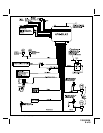
CONTROL MODULE:
The Control Module is NOT waterproof, DO NOT mount it in the Engine Compartment. Select a mounting location
under the dashboard. Choose a mounting location that will not interfere with proper operation of the vehicle's
steering column mechanism, brake and gas pedals. Secure the Control Module in the chosen location. Wait until
all components have been installed and all connections are made before plugging in the main connectors.
SIREN:
Select a location in the engine compartment that is not accessible from below the vehicle. The selected location
must be clear of hot or moving parts within the engine compartment The siren must be pointed downward to
prevent water retention and the flared end must be pointed away from and out of the engine compartment for
maximum sound distribution. Before securing the siren, check behind your chosen location to assure that the
mounting screws will not penetrate any factory wiring or fluid lines. Secure the siren mounting bracket using #8 self
taping screws by first using the mounting bracket as a template, scribe or mark the three bracket mounting holes.
Drill the three marked holes using a 1/8" drill bit, than mount the siren using #8 sheet metal screws.
VALET/PROGRAM/MANUAL OVERRIDE SWITCH :
Since much of the use of this switch by the vehicle operator requires concurrent operation of the ignition key switch,
it is recommended that the Valet/Program/Manual Override Switch be placed such that it can be reached by the
driver's left hand, while they operate the ignition key switch with their right hand. It is also highly recommended that
this switch be concealed to provide the highest level of security. The switch can be mounted to the lower dash
panel in the driver's area. Inspect behind the chosen location to insure that adequate clearance is allowed for the
body of the switch, and also that the drill will not penetrate any existing factory wiring or fluid lines. Drill a 1/4" hole
in the desired location and mount the switch by passing it through the panel from the opposite side. Secure the
switch using the nut, star-washer, and on/off face plate. It is suggested that the switch be oriented to allow the on
position to be up toward the driver and the off position to be down or away from the driver. Route the switch’s wires
and connector toward the location of the Control Module.
DASH MOUNTED L.E.D.:
The small Red LED included in the kit serves as a visual indicator of the system's status and provides a visual
deterrent to a potential thief. The LED also provides important feed back information during the transmitter and
feature program modes. The LED should be installed in the dashboard in a highly visible area that may be seen
from the driver’s seat as well as from outside the vehicle. Try to choose a location close enough to the Control
Module so that the LED's wires will reach. Carefully inspect the area behind your chosen location to insure that the
drill will not penetrate any existing factory wiring or fluid lines. Drill a 1/4" hole and pass the connector end of the
LED through the hole, and route the wires toward the location of the Control Module. Press the LED firmly into place
until it is fully seated.
HOOD AND TRUNK PIN SWITCHES:
The pin switch included in this package is intended for protecting the hood or trunk/hatch areas of the vehicle. In all
cases, the switch must be mounted to a grounded metal surface. When the pin switch is activated, (hood/trunk
open), it will supply a ground to the input wire thus activating the alarm. Mount the switch in the hood or trunk
locations away from water drain paths. If necessary, the included bracket may be used to move the switch away
from rain gutters or allow mounting to the firewall behind the hood seal. In both cases the switch must be set up to
allow the hood or trunk door to depress the switch at least 1/4 inch when the hood or trunk is closed and fully
2
128-5560A
2 of 8