


4
128-5560A
4 of 8
hatch is opened, and vice-versa. If only the hood, or only the trunk/hatch is connected to the Dark Green wire, no
diode is needed.
Note: The diodes which may be required for certain types of installations are the common 1N4000 series type. You
may chose to use any of the diodes in this series, with the 1N4003 and 1N4007 being the most common types. The
diodes must be installed with careful regard for their direction of current flow.
Note: This wire will be shunted when remote control channel 2 is accessed, (trunk release). This wire will remain
shunted all the while there is ground present and for 5 seconds after the ground is removed. This allows the operator
to open the trunk via the remote transmitter without having to first disarm the alarm system.
WHITE/BLACK Wire: Siren Output Wire
This wire provides a positive output (3A Max.) designed to directly drive a standard electronic siren. Find a suitable
mounting location for the siren and mount it properly. Run the Red wire of the siren into the passenger compart-
ment to the location of the APS-20LAD. Connect the White/Black wire to the Red wire from the siren. The Black
wire from the siren should then be securely grounded to the vehicle chassis.
BLACK Wire: Main System Ground
This is one of the most important wires of the APS-20LAD installation. It must be connected properly to a solid
chassis ground it will help ensure reliable system operation. Special care must be taken to locate a clean metal part
of the chassis as an attachment point for this wire. Some installers prefer to locate a sturdy metal bolt under the
dashboard or at the kick panel, and use it as the attachment point.
If you find a suitable factory bolt that reads ground when tested, attach a insulated ring terminal connector to the Black
wire, remove the bolt, place the red ring terminal over the bolt and reinstall it, tightening it securely. If you choose
instead to drill your own mounting hole into the vehicle's chassis, be certain to remove any paint or grease and
secure the ring terminal.
ORANGE Wire: Ground When Armed Output (Optional relay required.)
This wire provides a 300mA ground output when the alarm circuit is armed to control the starter inhibit relay.
Connect the Orange wire to terminal #86 of a standard SPDT relay. Connect terminal #85 of the relay to an ignition
wire in the vehicle that is +12VDC when the ignition key is turned to the on and start positions and off when the key
is in the off position. Locate and cut the low current starter solenoid wire found at the vehicle's ignition switch
harness. This wire will have +12VDC when the ignition key is moved to the start (crank) position and will have 0
volts in all other key positions.
Connect one side of the cut wire to terminal #87a of the relay. Connect the other side of the cut wire to terminal #30
of the relay.
DARK BLUE Wire: Delayed 300mA Pulsed, Channel 2 Output
The Dark Blue wire supplies a 300mA ground pulsed output whenever channel two of the receiver is accessed.
Pressing the transmitter Option button for three seconds will access Channel 2. This is a low current output and
must be connected to a relay to supply power to the trunk release or the circuit you wish to control. Connect the
Dark Blue wire to terminal # 86 of a VF45F11 P&B relay or equivalent. Connect terminal # 85 of the relay to a fused
+12VDC source. Connect the common, normally open, and normally closed contacts of the relay to perform the
selected function of Channel 2.
DOOR LOCK/UNLOCK CONTROL HARNESS (+) and (-)
2-PIN White Plug w/2 Wires; RED & GREEN
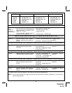
The Red and Green Door Lock/Unlock output wires provide either a momentary pulsed ground (-) or a momentary
pulsed 12VDC (+) output for controlling a vehicle's power door lock/unlock circuit. In order to accomplish this "dual
polarity" output scheme these two wires produce the opposite polarity at the opposite time. To better understand
this, refer to the table below:
The output of these wires has a maximum switching capability of 300mA. Many vehicles today have factory door
lock relays which can be connected directly to these outputs, however always confirm that the factory relays in your
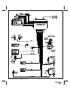
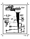
particular vehicle do not exceed the rated 300mA output of the units door lock/unlock circuit. Plug the two pin
connector of the door lock/unlock harness into the mating connector shell of the control module. Determine the
door lock circuit of the vehicle you are working on and wire according to the diagrams shown.
WIRING FOR "GROUND PULSE" DOOR LOCK CIRCUITS:
This is a system commonly used on most import vehicle's factory door lock/unlock systems, and with a few domes-
tic vehicles which employ factory "keyless entry" systems. In this application, the Red wire serves as the "Lock"
output, providing a ground pulse during the arming sequence, and the Green wire serves as the "Unlock" output,