


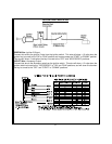
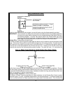
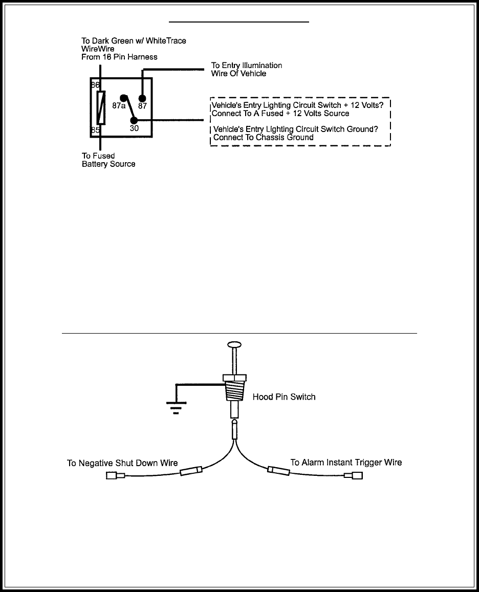
Entry Illumination Detail
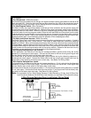
Grey w/ Black Trace Negative Inhibit Safety Shut Down Detail
9
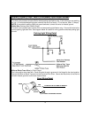
switch is to be used with an alarm system, connect this wire using the diode assembly provided.
IMPORTANT! This connection is a safety wire and must be connected as shown and tested as specified.
Failure to do so may result in personal injury or property damage. See detail of wiring in
the following diagram. This wire may also be used if the vehicle brake light circuit
switches ground to the brake lights. An isolation diode must be used for ground switched
brake light circuits and must be connected to the output of the brake switch.
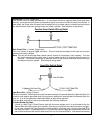
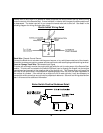
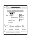
Orange Wire: Ground When Armed Output
This wire provides a 300 mA ground output when the alarm circuit is armed to control the starter inhibit
relay. Connect the Orange wire to terminal #86 (orange wire) of the relay provided. Connect terminal
#85 (red wire) of the relay to an ignition wire in the vehicle that is +12 volts when the ignition switch is
turned to the on and start positions and off when the key is off. Locate and cut the low current start
solenoid wire found at the vehicles ignition switch harness. This wire will have + 12 volts when the
ignition key is moved to the start (crank) position and will have 0 volts in all other key positions. Connect
one side of the cut wire to terminal #87a ( Black wire) of the relay. Connect the other side of the cut wire
to terminal #30 (White/Black wire) of the relay. See below for detail of wiring, also see Yellow Start wire
detail for connection to vehicle considerations.
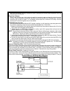
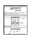
Brown w/ Black Trace Wire: Positive Inhibit Input
The Brown w/ Black Trace wire provides an instant shutdown for the Remote Start Control module
whenever it gets + 12 volts. If the Brake lights switch in the vehicle switches + 12 volts to the brake light
circuit, connect the Brown w/ Black trace wire to the output side of the brake switch. This will allow the