


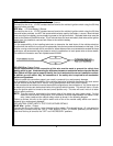
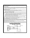
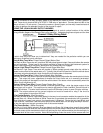
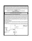

Channel 2 Relay Wiring Detail
12
and will remain active for as long as the transmitter button(s) is held. This is a low current output and
must be connected to a relay to supply power to the device you intend to control. Connect Green w/
Black Trace wire to terminal #86 of a VF45F11 P&B relay or equivalent. Connect terminal #85 of the
relay to a fused + 12 volt source. Connect the common, normally open, and normally closed contacts of
the relay to perform the selected function of the channel 3 output.
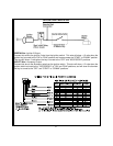
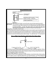
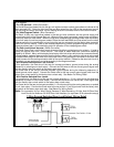
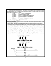
WIRING THE 4 PIN AUXILIARY OUTPUT HARNESS
The auxiliary 4 pin connector provides low current outputs to control various functions in the vehicle
during different stages of the Remote Start unit's operation. Understanding these outputs and the time
in which they occur will allow you to determine if they are needed for the particular vehicle you are
working on as well as how to use them.
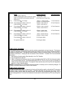
Black w Blue Trace Wire: Pulsed Ground Output Before Start
The Black w/ Blue Trace wire will provide a 300 mA pulsed ground output 3 seconds before the remote
start unit activates. Typical use for this output would be to disarm a factory theft deterrent system to
prevent false triggering of the factory alarm when the remote start unit engages.
Black w/ Light Green Trace Wire: Pulsed Ground Output After Start
The Black w/ Light Green Trace wire will provide a 300ma pulsed ground output after the vehicle is
started under control of the remote start unit. Typically this wire will be used to re-lock the vehicle doors
if the doors unlock automatically when the factory anti-theft system is disarmed.
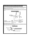
Black w/ Red Trace Wire: Pulsed Ground Output After Shutdown
The Black w/ Red Trace wire will provide a 300 mA pulsed ground output after the remote start unit shuts
down. This output will occur regardless of whether the circuit times out or is manually terminated.
Typically this output will be used to re-lock the vehicle doors if the doors unlock automatically when the
ignition circuit transitions to off.
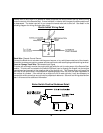
Black w/ Yellow Trace Wire: Ground Output During Start (Crank)
The Black w/ Yellow Trace wire will provide a 300 mA ground output while the starter output of the
remote start unit is active. This output can be used to activate the Crank Low/Bulb Test wire found in
some GM vehicles. This wire is also referred to as the ECM wake up wire in some Chrysler vehicles.
NOTE: The outputs above are low current outputs and must be used with a relay if the circuit's
requirement is more than 300 mA.
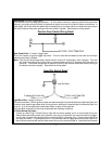
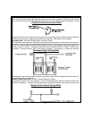
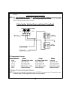
2 Pin Control Switch: (Red Connector)
The Black & Black w/White Trace wires loaded in the two pin red connector enable the operation of the
Remote Start unit. When the Black w/ White Trace wire is grounded, the remote start unit is operable.
When this wire is open from ground, the remote start is disabled. Route the twin lead Black and
Black w/White Trace wires from the control switch to the remote start unit and plug red two pin connec-
tor into the mating red two pin connector shell of the control module.
4 Pin Shock Sensor: (White Connector)
The Red (+12 volt), Black (ground), Blue (pre-detect) and Green (full trigger when armed) wires loaded
into the white connector shell are the inputs/outputs of the shock sensor. Route the 4 wire harness from
the shock sensor to the remote start control unit and plug the 4 pin white connector into the mating 4 pin
connector shell of the control module. Note: While operating under the control of the remote start unit