


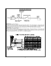
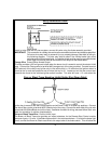
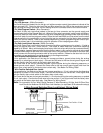

THE RANGE EXTENDER ANTENNA:
The range extender antenna provided with this unit allows routing from below the dash board for maximum
operating range. Choose a location above the belt line (dashboard) of the vehicle for best reception.
Special considerations must be made for windshield glass as some newer vehicles utilize a metallic shielded
window glass that will inhibit or restrict RF reception. In these vehicles, route the exposed, (non shielded)
end toward a rear window location for best reception. Secure the exposed end with double stick tape or
instant stick glue. After securing the exposed end of the antenna with the tape or glue, we advise also
securing a section of the antenna cable to a fixed support. This will prevent the antenna from dropping
down in case the double stick tape is exposed to extreme heat which may loosen it's gummed surface.
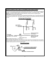
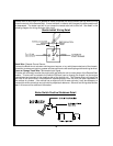
VALET/PROGRAM/MANUAL OVERRIDE SWITCH :
Select a mounting location that is easily accessible to the operator of the vehicle. It is not necessary to
conceal the switch however concealment is recommended as it offers a higher level of security. The
switch can be mounted to the lower dash panel in the drivers area. Inspect behind the chosen location to
insure that adequate clearance is allowed for the body of the switch, and also that the drill will not penetrate
any existing factory wiring or fluid lines. Drill a 1/4" hole in the desired location and mount the switch by
passing it through the panel from the underside. Secure the switch using the nut, star washer, and on/off
face plate. It is suggested that the switch be oriented to allow the on position to be up toward the driver and
the off position to be down or away from the driver. Route the switch's connector toward the control module.
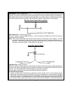
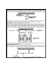
CONTROL SWITCH:
Select a mounting location known and accessible to the operator of the vehicle. A lower dash panel, kick
panel, or glove box is desirable. Inspect behind the chosen location to insure that adequate clearance is
allowed for the body of the switch, and also that the drill will not penetrate any existing factory wiring or fluid
lines. Drill a 1/4" hole in the desired location and mount the switch by passing it through the panel from the
underside. Secure the switch using the nut, star washer, and on/off face plate. It is suggested that the
switch be oriented to allow the on position to be up toward the driver and the off position to be down or
away from the driver. Route the switch's connector toward the control module. Place the RED rubber boot,
included in the kit, over the switch handle to differentiate this switch from the valet/program switch.
SHOCK SENSOR:
Select a centrally located, solid mounting surface for the shock sensor that will allow consistent operation
from all areas of the vehicle. The selected location must be within 18" of the control module to allow
routing and connecting of the 4 pin harness. Secure the shock sensor to the chosen location using two #8
self taping sheet metal screws. The sensor can also be secured to an existing dash brace using cable tie
straps. Whichever mounting method is used be sure to allow access to the sensitivity adjustment poten-
tiometer for use later in the installation.
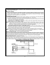
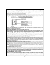
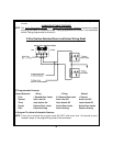
STARTER INHIBIT RELAY:
Select a mounting location within 12" of the ignition switch's low current start solenoid wire. Secure the
relay to an existing harness in the chosen location using a cable tie around the relay's wiring harness.
Caution! Do not wire tie the metal bracket to an existing wiring harness as vibration may cause chaffing
and shorting damaging the factory wiring. If an existing harness is not available then secure the
relay's metal mounting tab to an under dash metal brace with a #8 self taping sheet metal screw.
Wire the relay as per the diagram found later in this manual.
The AA-RS20CS is to be used in vehicles with AUTOMATIC TRANSMISSIONS only! Although this
combination Alarm/Remote Start unit is a sophisticated system with many advanced features, IT MUST
NOT be installed into a vehicle with a manual operated transmission. Doing so may result in serious
personal injury and property damage.
IMPORTANT!
DO NOT PLUG THE SIX PIN MAIN POWER HARNESS OR THE MULTI PIN INPUT / OUTPUT HARNESS
INTO THE CONTROL MODULE UNTIL ALL CONNECTIONS TO THE VEHICLE HAVE BEEN MADE.
AFTER SELECTING YOUR TARGET WIRES AS DEFINED BELOW, DISCONNECT THE NEGATIVE
BATTERY CABLE FROM THE VEHICLE BATTERY PRIOR TO MAKING ANY CONNECTIONS.
3