


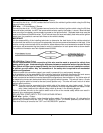
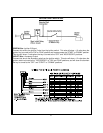
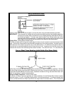
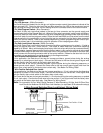
General Motors VATS By-Pass Diagram
8
Start unit is activated, the relay contacts will open, preventing the shock sensor's operation until the
Remote Start unit shuts off.
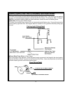
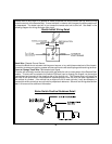
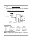
B. Ignition 3 Output:
Some newer vehicles use a third ignition wire which is required to start and keep the vehicle's engine
running. If this is the case, connect the Light Blue wire to terminal #86 of an external relay. Connect
terminal # 30 & # 85 to a fused + 12 volt battery source rated for a minimum of 25 Amp. Connect
terminal # 87 to the third ignition wire in the vehicle.
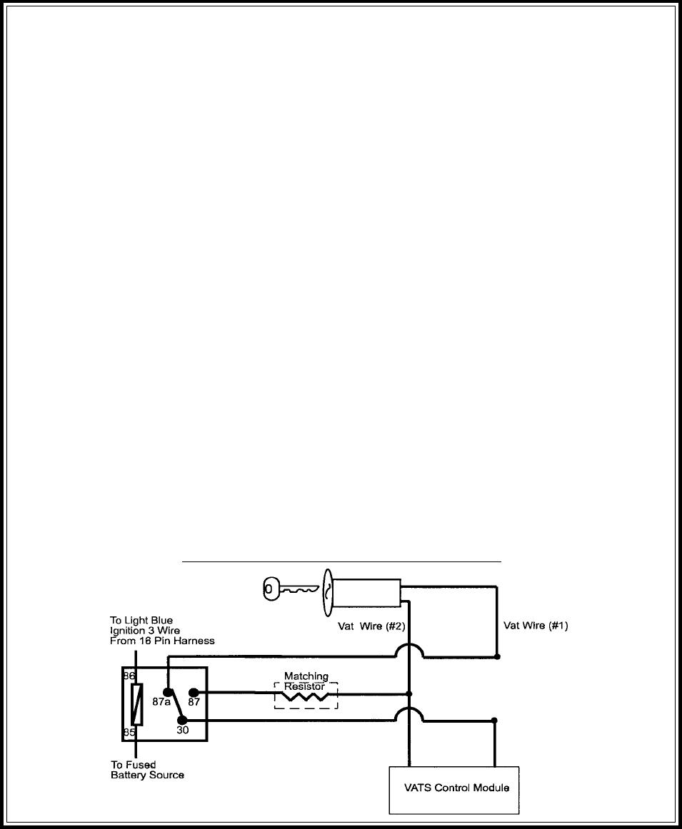
C. GM VATS Key Override:
If the vehicle has the General Motors VATS system installed, you will need to by-pass the system while
the vehicle is operating under the control of the Remote Start Unit. To Do This;
1. Measure the resistance of the resistor pellet on the ignition key then select a resistor within 5% of the
key's value from the resistor pack supplied.
2. Locate the pair of VATS wires in the vehicle, usually a pair of thin gauge wires running from the
ignition switch to the VATS control module.
NOTE: These wires are typically White w/ Black trace and Violet w/ Yellow trace, however in later model
Cadillacs, they are run through an orange sleeve, and are either both Black, both Yellow, or both
White wires. Consult the factory service manual for additional information.
3. Connect the Light Blue Wire from the Remote Start Unit to terminal #86 of an external relay. Connect
terminal #85 of the relay to a fused + 12 volt battery source.
4. Cut (#1) wire (as shown), and connect the ignition switch side of the cut wire to terminal #87a of the
relay. Connect the other side of the (#1) wire to terminal #30.
5. Connect the previously selected resistor from terminal #87 to the second (#2) wire (as shown).
NOTE: The above information and following diagram is for the GM VATS system only. For GM PASS
LOCK System you will require the Audiovox AS-PASS II Module.
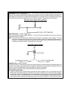
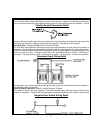
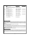
Green w/ White trace Wire: Entry Illumination Ground Output
This wire provides a 30 second ground output (300 mA Max.) whenever the remote is used to disarm the
alarm or to unlock the doors and provides a continuous pulsed output whenever the alarm is triggered.
This wire should be connected to an external relay, and wired to the vehicles interior entry lighting
whenever the optional Interior Illumination circuit is desired. See below for relay wiring details.
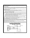
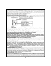
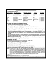
Grey w/ Black Trace Wire: Negative Inhibit Input
The Grey w/ Black Trace wire provides an instant shutdown for the Remote Start Control Module when-
ever it is grounded. Connect the Grey w/ Black trace wire to the hood pin switch previously installed. This
wire must be routed through a grommet in the firewall and connected to the hood pin switch. If the pin