


128-7853
7 of 16
7
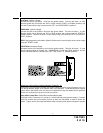
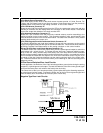
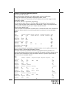
Orange: Ground While Armed Output
This wire provides a 300 mA ground output when the alarm circuit is armed to control the
starter inhibit relay. Connect the Orange wire to terminal #86 (orange wire) of the relay
provided. Connect terminal #85 (red wire) of the relay to an ignition wire in the vehicle that is
+12 volts when the ignition switch is turned to the on and start positions and off when the key
is off. Locate and cut the low current start solenoid wire found at the vehicles ignition switch
harness. This wire will have + 12 volts when the ignition key is moved to the start (crank)
position and will have 0 volts in all other key positions. Connect one side of the cut wire to
terminal #87a ( Black wire) of the relay. Connect the other side of the cut wire to terminal #30
(White/Black wire) of the relay.
White w/ Black Trace Wire: (+) Siren Output
This is the positive siren feed wire. Route this wire through a grommet in the firewall to the
siren location. Connect the White w/ Black Trace wire to the Red wire of the Siren. Secure the
Black wire of the Siren to a known chassis ground or solid clean metal surface.
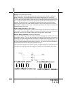
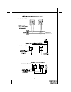
Green w/ Orange Trace Wire: Tachometer Input Signal
This wire will continually monitor the engine's tach rate while the unit is under power of the
Remote Start module. This wire will be routed to the vehicle ECM tach input or through the
firewall into the engine compartment and connect to the negative side of the ignition coil. This
Remote Start unit learns the tach rate of the vehicle and in most cases will operate properly from
one multi coil pack regardless of the number of cylinders. This unit can also be connected to an
injector wire and will monitor the injector instead of the tach.
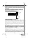
If the vehicle has a single coil unit for each cylinder, it may be necessary to connect this wire to
more than one cylinder for proper tach reference. See Multi Coil Pack Adaptor shown below.