


128-7853
11 of 16
11
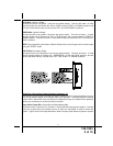
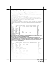
4 Pin Shock Sensor Connector “D”
Red, Black Green & Blue wires of the shock sensor harness provide +12 Volts, Ground, Full
Trigger, and Pre-Detect inputs to and from the sensor. Route these wires from the previously
installed sensor and connect to the mating connector on the control module.
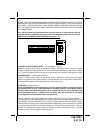
2 Pin LED Harness, Connector “E”
Route the twin lead Red and Blue wires from the LED to the remote start control unit and plug
the two pin connector into the mating white mini connector on the control module. These wires
control the anode and cathode of the dash mounted LED.
4 Pin Antenna/Transceiver, Connector “F”
Route the 4 pin connector from the previously installed antenna receiver assemble to the
mating connector on the control module. This connector supplies 5 volts, ground and RF data
from the antenna receiver to the remote start module. Be certain this connector is firmly seated
making good contact to the control unit.
2 Pin Valet/Program/Override Pushbutton Switch, Connector “G”
The Black & Black/Gray twin lead wires loaded in the two pin blue connector are the ground
supply and program/valet/override input of the Remote Start unit. Route the two wires from the
previously installed Push-Button switch to the mating connector on the control module.
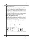
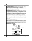
Wiring The 2 Pin Door Lock/Unlock Harness Connector “H”:
The Red & Green Door Lock/Unlock output wires provide a pulsed ground output to control the
vehicle door lock / unlock circuits. The output of these wires has a maximum switching capa-
bility of 250 mA. Many vehicles today have factory door lock relays which can be connected
directly to these outputs, however always confirm that the factory relays in your particular vehicle
do not exceed the rated 250 mA output of the units door lock/unlock circuit. Plug the 2 pin
connector of the door lock/unlock harness into the mating connector shell of the control mod-
ule. Determine the door lock circuit of the vehicle you are working on and wire according to the
diagrams shown.
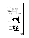
3 Wire Ground Switched Door Lock Circuits:
In this application, the Red wire of the 2 pin harness provides a ground pulse during the arming
sequence, or pulsed ground lock output. Connect the Red wire to the low current ground signal
wire from the factory door lock switch to the factory door lock relay.
The Green wire of the 2 pin harness provides a ground pulse during the disarming sequence,
or pulsed ground unlock output. Connect the Green wire to the low current ground signal wire
from the factory door unlock switch to the factory door unlock relay.
Negative Type Door Lock Circuits