


128-7853
3 of 16
3
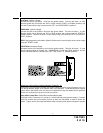
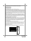
SIREN:
Select a location in the engine compartment that is not accessible from below the vehicle. The
selected location must be clear of hot or moving parts within the engine compartment The
siren must be pointed downward to prevent water retention and the flared end must be pointed
away from and out of the engine compartment for maximum sound distribution. Before secur-
ing the siren, check behind your chosen location to assure that the mounting screws will not
penetrate any factory wiring or fluid lines. Secure the siren mounting bracket using #8 self
taping screws or by first using the mounting bracket as a template, scribe or mark the mounting
holes. Drill the marked holes using a 1/8" drill bit, then mount the siren using #8 sheet metal
screws.
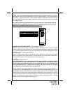
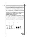
HOOD PIN SWITCH:
The pin switch included in this package are intended for protecting the hood area of the vehicle.
In all cases, the switch must be mounted to a grounded metal surface. When the pin switch is
activated, (hood/trunk open), it will supply a ground to the input wire activating the alarm. In
addition, the hood switch is required for the safety shut down of the remote start unit. If the
vehicle is being worked on, this hood switch prevents the remote start activation even if the RF
command to start is issued. This switch must be installed in all applications. Failure to do
so may result in personal injury or property damage.
Mount the switch in the hood locations away from water drain paths. If necessary, the included
bracket may be used to move the switch away from rain gutters or allow mounting to the firewall
behind the hood seal. In both cases the switch must be set up to allow the hood to depress the
switch at least 1/4 inch when the hood is closed and fully extended when the hood is opened. For
direct mounting, a 1/4 inch hole must be drilled. Carefully check behind the chosen location to
insure the drill will not penetrate any existing factory wiring or fluid lines.
Drill a 1/4" hole in the desired location and thread the pin switch into it using a 7/16" nut driver
or deep well socket. If using the mounting bracket, first secure the bracket to the desired
location and secure the pin switch in the pre-threaded mounting bracket hole.
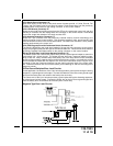
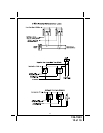
STARTER INHIBIT RELAY:
Select a mounting location within 6" of the ignition switch's low current start solenoid wire.
Secure the relay to an existing harness in the chosen location using a cable tie around the
relay's wiring harness.
CAUTION! Do not wire tie the metal bracket to an existing wiring harness as vibration may
cause chaffing and shorting damaging the factory wiring. If an existing harness is not available
then secure the relay's metal mounting tab to an under dash metal brace with a #8 self tapping
sheet metal screw. Wire the relay as per the diagram found later in this manual.
SHOCK SENSOR:
Select a centrally located, solid mounting surface for the shock sensor that will allow consis-
tent operation from all areas of the vehicle. The selected location must be within 24" of the
control module to allow routing and connecting of the 4 pin harness. Secure the shock sensor
to the chosen location using two #8 self tapping sheet metal screws. The sensor can also be
secured to an existing dash brace using cable tie straps. Whichever mounting method is used
be sure to allow access to the sensitivity adjustment potentiometer for use later in the installa-
tion.