


128-7853
5 of 16
5
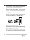
BLUE Wire: Ignition 1 Output
Connect this wire to the ignition 1 wire from the ignition switch. This wire will show +12 volts
when the ignition key is turned to the "ON" or "RUN" and the "START" or CRANK" positions, and
will have 0 volts when the key is turned to the "OFF" and "ACCESSORY" positions.
GREEN Wire: Ignition 2 Output
Connect this wire to the ignition 2 wire from the ignition switch. This wire will show + 12 volts
when the ignition key is turned to the "ON" or "RUN" position and is some cases the "START" or
CRANK" position. This wire will show 0 volts when the key is turned to the "OFF" and "ACCES-
SORY" positions.
NOTE: See programming information (Bank 3 Selection # 6) concerning this wire to allow output
during the "START" mode.
VIOLET Wire: Accessory Output
Connect this wire to the Accessory wire from the ignition switch. This wire will show + 12 volts
when the ignition switch is turned to the "ACCESSORY" or "ON" and "RUN" positions, and will
show 0 volts when the key is turned to the "OFF" and "START" or "CRANK" positions.
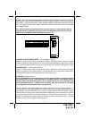
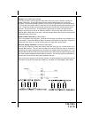
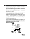
Wiring The 4 Pin Auxiliary Output Harness, Connector “A”
The auxiliary 4 pin connector provides low current outputs to control various functions in the ve-
hicle during different stages of the Remote Start unit's operation. Understanding these outputs
and the time in which they occur will allow you to determine if they are needed for the particular
vehicle you are working on as well as how to use them.
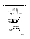
Black w Blue Trace Wire: Pulsed Ground Output Before Start
The Black w/ Blue Trace wire will provide a 1 second 250 mA pulsed ground output 1.5 second
before the remote start unit activates as well as when the transmitter is used to disarm the
system. Typical use for this output would be to disarm a factory theft deterrent system to prevent