


ASUS P2V User’s Manual 49
IV. BIOS SOFTWARE
IV. BIOS
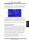
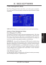
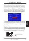
Power Management
PWR Up On Modem Act (Enabled)
This allows either settings of Enabled or Disabled for powering up the computer (turns the
ATX power supply on) when the modem receives a call while the computer is Soft Off.
NOTE: The computer cannot receive or transmit data until the computer and appli-
cations are fully running, thus connection cannot be made on the first try. Turning
an external modem off and then back on while the computer is off causes an initializa-
tion string that will also cause the system to power on.
AC PWR Loss Restart (Disabled)
This allows you to set whether you want your system to boot up after the power has
been interrupted. Disabled leaves your system off after reapplying power and En-
abled boots up your system after reapplying power.
Wake On LAN (Enabled)
This allows you to remotely power up your system through your network by send-
ing a wake-up frame or signal. With this feature, you can remotely upload/download
data to/from systems during off-peak hours. Set to Enabled to set this feature.
IMPORTANT: This feature requires the ASUS PCI-L101 LAN Card (see VII. ASUS
LAN Card) and an ATX power supply with at least 720mA +5V standby power.
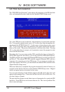
Automatic Power Up (Disabled)
This allows you to have an unattended or automatic power up of your system. You may
configure your system to power up at a certain time of the day by selecting Everyday,
which will allow you to set the time or at a certain time and day by selecting By Date.
.....................................................................................................................................
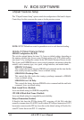
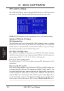
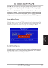
Fan Monitor (xxxxRPM)
The onboard hardware monitor is able to detect the Chassis Fan Speed, CPU Fan
Speed, and the Power Supply Fan Speed in Rotations Per Minute (RPM). These
values refresh upon any key entries in the BIOS setup screen. Set to Ignore if one of
these are not used so that error messages will not be given.
.....................................................................................................................................
Thermal Monitor (xxxC/xxxF)
The onboard hardware monitor is able to detect the CPU and MB (motherboard) tem-
peratures. These values refresh upon key entries. Set to Ignore only if necessary.
.....................................................................................................................................
Voltage Monitor (xx.xV)
The onboard hardware monitor is able to detect the voltages put out by the voltage
regulators. These values refresh upon key entries. Set to Ignore only if necessary.
NOTE: If any of the monitored items are out of range, an error message will appear:
“Hardware Monitor found an error, enter POWER MANAGEMENT SETUP for
details”. You will then be prompted to “Press F1 to continue, DEL to enter SETUP”.