


ASUS P2V User’s Manual 11
III. INSTALLATION
Jumpers
1) KBPWR p. 12 Keyboard Power
2) AGPFS p. 13 AGP Frequency Selection
3) VIO p. 13 Voltage Input/Output Selection
4) FS0, FS1, FS2, FS3 p. 14 CPU External Clock (BUS) Frequency Selection
5) BF0, BF1, BF2, BF3 p. 14 CPU Core:BUS Frequency Multiple
Expansion Slots/Sockets
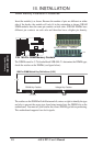
1) System Memory p. 17 System Memory Support
2) DIMM Sockets p. 18 DIMM Memory Module Support
3) CPU Slot 1 p. 19 Pentium II/Celeron CPU Support
4) SLOT1, SLOT2, SLOT3 p. 24 16-bit ISA Bus Expansion Slots
*
5) PCI1, PCI2,PCI3, PCI4 p. 24 32-bit PCI Bus Expansion Slots
6) AGP p. 25 Accelerated Graphics Port
Hardware Monitor
1) JTPWR, JTCPU p. 23 Thermal Sensor Connector
Connectors
1) PS2KBMS p. 26 PS/2 Keyboard Connector (6-pin female)
2) PS2KBMS p. 26 PS/2 Mouse Connector (6-pin female)
3) PARALLEL p. 27 Parallel (Printer) Port Connector (25-pin female)
4) COM1, COM2 p. 27 Serial Port COM1 & COM2 (two 9-pin male)
5) FLOPPY p. 27 Floppy Drive Connector (34-pin block)
6) USB p. 28 Universal Serial BUS Ports 1 & 2 (two 4-pin female)
7) Primary/Secondary IDE p. 28 Primary/Secondary IDE Connector (40-pin blocks)
8) IDELED p. 28 IDE LED Activity Light (2 pins)
9) CHA_, PWR_, CPU_FAN p. 29 Chassis, Power Supply, CPU Fan Power Lead (3-pin block)
10) CHASIS p. 29 Chassis Intrusion Alarm Lead (4-1 pins)
11) IR p. 30 Infrared Port Module Connector (5 pins)
12) ATXPWR p. 30 ATX Motherboard Power Connector (20-pin block)
13) WOL_CON p. 31 Wake on LAN Connector (3 pins)
14) SMB p. 31 SMBus Connector (5-1 pins)
15) MSG.LED (PANEL) p. 32 System Message LED (2 pins)
16) SMI (PANEL) p. 32 SMI Switch Lead (2 pins)
17) PWR.SW (PANEL) p. 32 ATX Power & Soft-Off Switch Lead (2 pins)
18) RESET (PANEL) p. 32 Reset Switch Lead (2 pins)
19)
PWR.LED (
PANEL
)
p. 32 System Power LED Lead (3 pins)
20)
KEYLOCK (
PANEL
)
p. 32 Keyboard Lock Switch Lead (2 pins)
21) SPEAKER (PANEL) p. 32 Speaker Output Connector (4 pins)
*
The onboard hardware monitor uses the address 290H-297H so legacy ISA cards must not
use this address otherwise conflicts will occur.
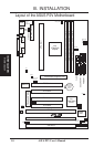
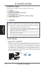
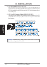
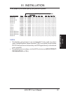
Board Layout
III. INST ALLATION