


ASUS P2V User’s Manual 29
III. INSTALLATION
Connectors
III. INST ALLATION
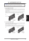
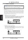
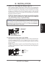
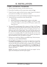
9. Chassis / CPU / Power Supply Fan Connectors (3-pin FAN)
These connectors support cooling fans of 500mA (6W) or less. Orientate the
fans so that the heatsink fins allow airflow to go across the onboard heatsink(s)
instead of the expansion slots. Depending on the fan manufacturer, the wiring
and plug may be different. The red wire should be positive, while the black
should be ground. Connect the fan’s plug to the board taking into consideration
the polarity of the this connector.
NOTE: The “Rotation” signal is to be used only by a specially designed fan
with rotation signal. The Rotations per Minute (RPM) can be monitored
using ASUS PC Probe Utility or Intel LDCM Utility.
WARNING! The CPU and/or motherboard will overheat if there is no airflow
across the CPU and onboard heatsinks. Damage may occur to the motherboard
and/or the CPU fan if these pins are incorrectly used. These are not jumpers,
do not place jumper caps over these pins.
P2V 12Volt Cooling Fan Power
Chassis Fan Power
CPU Fan Power
Power Supply Fan
GND
Rotation
+12V
R
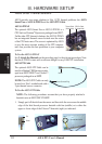
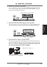
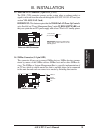
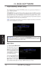
10. Chassis Intrusion Alarm Lead (4-1 pin CHASIS)
This requires an external detection mechanism such as a chassis intrusion moni-
tor/sensor or microswitch. The sensor is triggered when a high level signal is
sent to the CHASIS lead. This occurs when the side panel is opened or drive bay
doors are opened.
NOTE: When the chassis is opened, connect/short the Chassis Signal pin to the
+5VSB pin. When the chassis is opened, connect/short the Chassis Signal pin to
the Ground pin.
R
P2V Chassis Intrusion Alarm Lead
Ground
Chassis Signal
+5VSB