


26 ASUS P2V User’s Manual
5. External Connectors
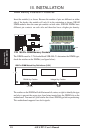
IMPORTANT: Ribbon cables should always be connected with the red stripe to
Pin 1 on the connectors. Pin 1 is usually on the side closest to the power connector
on hard drives and CD-ROM drives, but may be on the opposite side on floppy disk
drives. Check the connectors before installation because there may be exceptions.
IDE ribbon cables must be less than 46 cm (18 in.), with the second drive connector
no more than 15 cm (6 in.) from the first connector.
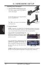
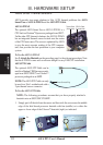
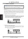
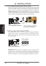
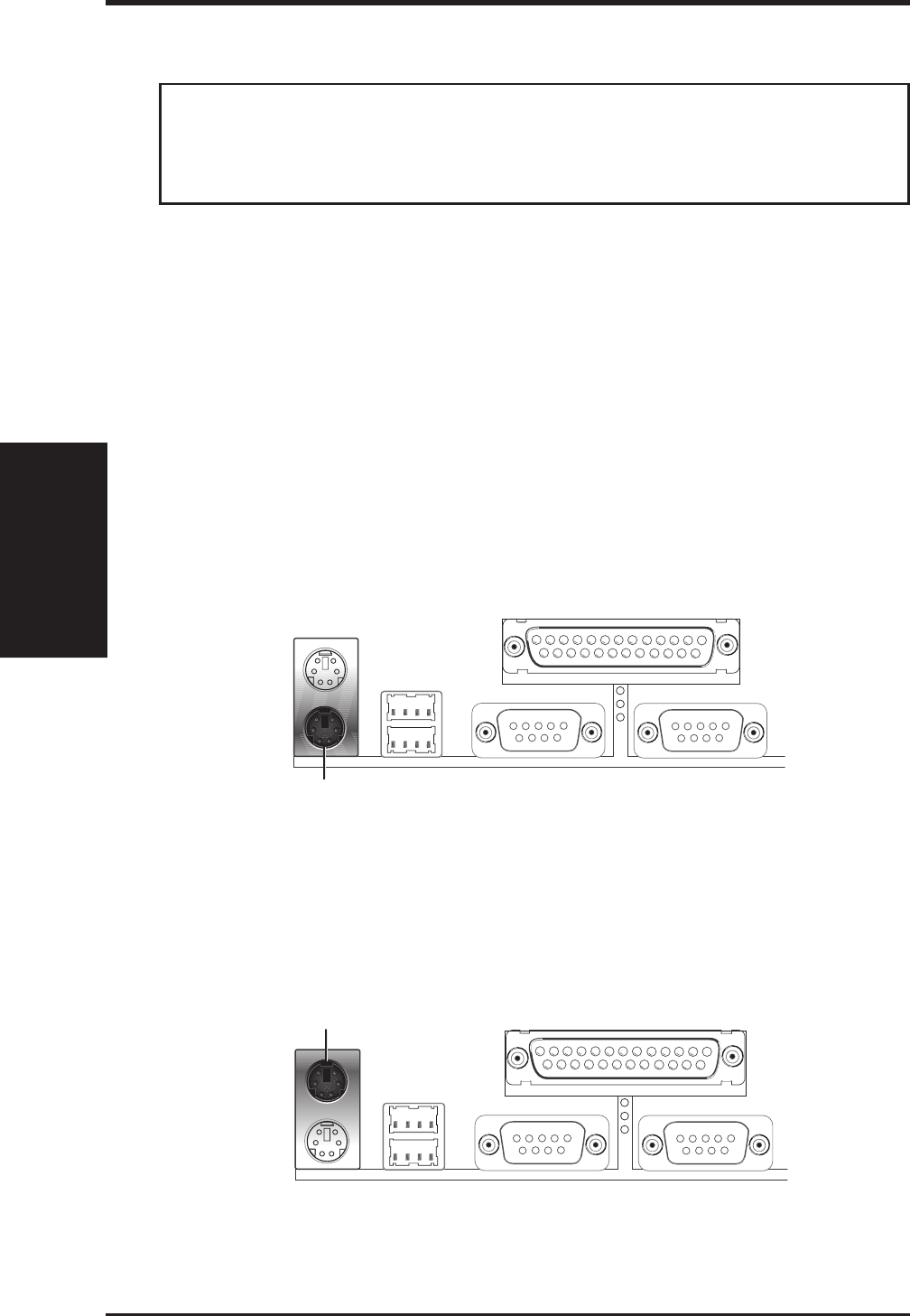
1. PS/2 Keyboard Connector (6-pin Female)
This connection is for a standard keyboard using an PS/2 plug (mini DIN). This
connector will not allow standard AT size (large DIN) keyboard plugs. You
may use a DIN to mini DIN adapter on standard AT keyboards.
PS/2 Keyboard (6-pin Female)
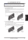
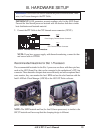
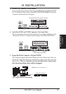
2. PS/2 Mouse Connector (6-pin Female)
The system will direct IRQ12 to the PS/2 mouse if one is detected. If not de-
tected, expansion cards can use IRQ12. See “PS/2 Mouse Control” in BIOS
Features Setup of the BIOS SOFTWARE.
PS/2 Mouse (6-pin Female)
WARNING! Some pins are used for connectors or power sources. These are
clearly distinguished from jumpers in the motherboard layout. Placing jumper
caps over these connectors will cause damage to your motherboard.
Connectors
III. INST ALLATION
III. INSTALLATION