


Installation Guide
Installation Guide
Recommended Pre-Installation Procedures
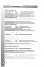
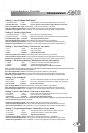
- Control module.
- 2 way Remote transmitter.
- Antenna with built in Program Button and LED’s.
- 6 pin main harness with dual 30amp power inputs.
- 14 pin harness.
- 4 pin square harness.
- 4 pin keyless entry harness.
- 4 pin Aux. sensor harness.
- Multi-tone siren.
- Hood pin safety switch.
- Hood and window stickers.
- Installation guide and Owner’s manual.
BEFORE STARTING INSTALLATION:
- Discuss the optional features with the customer.
- Take a few minutes to review the installation and owners manuals.
- Check if the vehicle has a factory security or anti-theft system.
*If equipped, inform the customer of addition parts and labour.
- Do a walk around the vehicle and check for any damage.
- If installing a LED discuss the placement with customer before installing.
Note: This remote starter is designed for fuel injected and diesel engines.
Recommended Installation Procedures
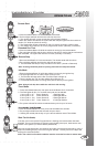
Under Hood Connections - Route the hood pin and tach wires through the firewall into the engine
compartment. Always try to pull the wires through a factory rubber grommet. If drilling through the firewall, BE
CAREFUL. Check for obstructions on both sides of the firewall. After drilling use a snap in grommet to protect
the wires from sharp edges.
Proper Connections - Remote Starters can handle loads of up to 30 amps for extended periods of time. It
is CRITICAL to insure that ALL high current connections are properly soldered and insulated with quality
electrical tape. Failing to insure proper connections will result in warranty being VOID and can result in a FIRE.
The manufacturer is not responsible for any such damages. It only takes a few more minutes to do the job
RIGHT.
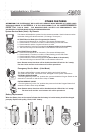
Mounting The Control Module - Never mount the module in the engine compartment. Select a location
under the dash to install the main module. Be certain that the module is securely attached and does not
obstruct any serviceable areas. Do not force or jam the module into tight places instead of mounting. The
module must be free from all moving parts such as brake, clutch and gas pedal linkages. Do not place the
module directly in front of a heater vent.
Installing the External Long Range Antenna - To insure the best possible reception, place the
antenna in the center of the windshield, behind the rear view mirror. Before attaching to the glass ensure that
the surface is clean and dry. For best results with range, place the antenna below the tint screen. Run the
cable under the headliner and behind the A-pillar panel. Be careful not to pinch the antenna cable. Plug the
antenna into the BLUE connector on the Control Module.
NOTE: This step is not used on Alarm Only Units with no External Antenna.
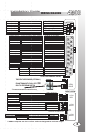
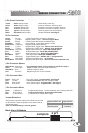
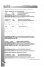
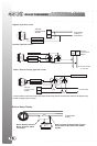
Yellow Starter 30amp output 12volts during crank only.
Green Heater 30amp output 12volts in accessory. Off during start.
Red 12 power 30amp input Constant 12volt power at ignition harness.
Red 12 power 30amp input Constant 12volt power at ignition harness.
Blue Ignition 1 30amp output 12volts in ignition and start positions.
White Selectable 30amp output Jumper Selectable. See Page 5.
Yellow Re-Arm 0.75sec Pulse With Lock And On Shutdown.
Orange (-) Output Negative While Locked - **Starter Program Mode.
Brown Disarm 0.75sec Pulse With Unlock And Before Start.
Red/White 3rd CH Trunk Release - Active When button 2 is held.
White/Violet (-)Running Negative Output While Running.
Green (-) Door Negative Door Trigger Input - Manual Trans And Alarm.
Purple (+) Door Positive Door Trigger Input - Manual Trans And Alarm.
Green/White Hood Pin Negative Hood Pin Input - MUST BE CONNECTED!!
Pink Brake Positive Brake Input - MUST BE CONNECTED!!
Black Ground System Ground Input - MUST BE CONNECTED!!
Blue/White Tach Tach Signal Input - MUST BE CONNECTED!!
Blue Glow Plug Programmable Input - DIESEL ONLY. **Programmable.
White Park Lights Positive Park light Output - 10 Amp Max.
Black/White Park Brake Negative Park Brake Input - Manual Transmission Models Only.
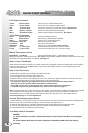
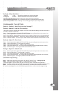
14 Pin Connector
White/Green Channel 4 Programmable Output. Press buttons #1 and #3 See Page 9.
Black Dome Light Negative Output For Dome Light Supervision.
White/Blue Siren Positive Output For Siren.
Red Trunk Pin Negative Input For Trunk Pin Switch.
Green Door Lock Door Lock Output - Programmable - See Page 8.
Red 12 Volts Low Current Output. Use With Voltage Inverter
Blue Door Unlock Door Unlock Output - Programmable - See Page 8.
Pink 2nd Unlock Door Unlock Output - Programmable - See Page 8.
4 Pin Connector Square
4 Pin Connector Red
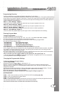
Jumper Selections
3 Pin Connector White
Green (-) Disarmed Programmable Output. (-) when disarmed, when cranking and LED.
Pink Horn/ Chan.5 Programmable Output. Press buttons #2 and #3.
Blue (+) Disconnect (+) Disconnect Or Instant Start Trigger.
The jumpers control the output on the white wire from the
six pin harness. Place the jumpers in the above order to
change the output.
Note: The default setting is second ignition.
Output on White wire Jumper position
Second Starter Position 1
Second Accessory Position 2
Second Ignition Position 3
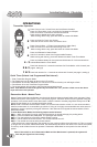
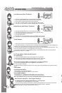
Components
Testing The System - When the installation is complete, it will be necessary to test that the system is
working correctly. The system’s default programming will work on the majority of vehicles, but might need to be
adjusted for some applications. If the installation requires special timing or additional features, proceed to
6 Pin Power Connector
5
ATTENTION: The Hood Pin Switch MUST always be connected!!
Program Mode.
Note: Always inform user to place system in Service Mode before any service work is performed
on the vehicle.
Back View Of Module
Jumpers
3 2 1
INSTALLATION TIPS
WIRING CONNECTORS
4