


Installation Guide
Installation Guide
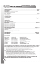
4500 Wiring Diagram Page 3
Pre-Installation Page 4
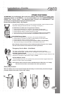
Components
Recommended Pre-Installation Procedures
Recommended Install procedures
Wire Connectors Page 5
6 Pin Connector
14 Pin Connector
4 Pin Red Connector
4 Pin Blue Connector
Jumper Selections
Installation Page 6-7
Basic Installation - Quick start
Plugging In The Module
Auto Tach Learn
Shock Sensor Programming
Programming Page 7-11
Program Overview & System Reset
Program Menu 1 (User Settings)
Program Menu 2 (Alarm Settings)
Program Menu 3 (Starter Settings)
Program Menu 4 (Tach Settings)
Programming The Transmitter
Other Features And Operations Page 12- 13
Transmitter Operation
Timer Mode
Reservation Mode (Manual Transmission Only)
Service Mode (Valet Mode)
Battery Replacement
System Operation Page 14-15
Relay Diagrams Page 16
TABLE OF CONTENTS
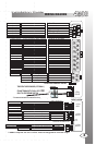
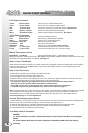
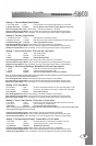
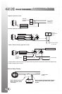
WIRING DIAGRAM
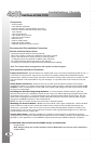
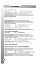
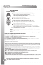
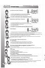
If the remote starter has a failed start attempt or if a safety input is activated the Diagnostic Memory will store up
to four shutdowns in memory. This information can then be accessed to determine the source of the shutdown.
To Enter Diagnostic Mode:
1 - Turn the ignition on wait two seconds then turn off. Press the Program Button and release.
2 - The system will respond with three park light flashes and the siren will chirp the
same number of times as the events in memory. ( Maximum four events, four chirps)
Note: If the siren does not chirp, there are no events in memory.
3 - Press the Program Button once to view the last shut down code. The siren will chirp once to
confirm code one. (If the siren does not chirp, there are no codes in memory).
4 - The LED’s on the antenna will flash a code corresponding to a shut down trigger. Press the
Program Button again to check the second code. The siren will chirp twice to confirm code two.
5 - To Clear Diagnostic Memory. While in Diagnostic Mode press and hold the Program Button for
five seconds. The park lights will flash and the siren will chirp once.
Note: Once diagnostic memory has 4 improper shutdown events in memory, the system will not
record any further shutdown events until the system memory has been cleared.
DIAGNOSTICS
3
11
33
55
22
44
66
22
11
44
33
66
55
77
88
1010
1010
99
1212
1212
1111
1111
1414
1313
1313
4 PIN
BLUE
4
PI
N
RED
4
N
PI
HW
I
TE
4PI
N
I
WHTE
4N
PI
H
W I
TE
ID
E
V ES I
W
SATELLITE LINK PLUG
STARTER DISABLE RELAY
***500ma outputs are low current and are designed to activate relays
Blue
Green
Red
Red
Yellow
White /Green
White /Blue
Red
Starter
Heater
Main Power
Ignition 1
Selectable
Main Power
FACTORY RE-ARM
STARTER DISABLE
FACTORY DISARM
TRUNK RELEASE
(-) WHEN RUNNING
(-) DOOR TRIGGER
HOOD PIN INPUT
(+) DOOR TRIGGER
BRAKE SWITCH
GROUND
TACH INPUT
GLOW PLUG
PARK LIGHTS
PARK BRAKE
4th Ch. Programmable
Siren Output
Dome Light Supervision
Trunk Pin Input
YELLOW
WHITE/VIOLET
BLUE/WHT
BROWN
ORANGE
GREEN/WHITE
WHITE
BLUE
GREEN
BLACK/WHITE
PURPLE
PINK
BLACK
RED/WHITE
Black
White
(+) 30amp Output
(+) 30amp Output
(+) 30amp Input
(+) 30amp Input
(+) 30amp Output
(+) 30amp Output
(-)500ma Output
(-)500ma Output
(-)500ma Output
(-)500ma Output
(-)500ma Output
(-)500ma Output
Buttons #1 & # 3
Buttons #2 & # 3
(-)500ma Output
Negative Input
Negative Input
Negative Input
Negative Input
Negative Input
(A/C) Input
(-) Input
Positive Input
Positive 15amp
Positive 3 amp
Positive Input
Green
Pink
Blue
Programmable
Horn Honk/ 5th Channel
(-)Disarmed/Cranking/LED
(-)500ma Output
(-)500ma Output
(+) Input
(+)Disconnect
Sensor Full-Warn Input
Sensor Pre-Warn Input
Sensor Ground Output
Sensor 12V+ Power Output
Black
Red
Blue
Green
(-)Input
(-) Input
(-)500ma Output
(+)500ma Output
Door Lock
12volt Inverter Output
Door Unlock
Passenger Door Unlock
Red
Blue
Pink
Green
(-)500ma Output
(+)500ma Output
(-)500ma Output
(-)500ma Output
FM ANTENNA WITH DUAL LED’S AND
BUILT-IN PROGRAM SWITCH.
*The antenna must be connected for the system to operate.
TEMPERATURE SENSOR (OPTIONAL)
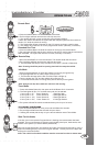
PARK LIGHTS STATUS LED DIAGNOSTIC CODE
3 Flashes Series of 3 Flashes Door Opened “M” Models
3 Slow Flashes LED’s On Solid System Is In Service Mode
4 Slow Flashes Series of 4 Flashes Not in Reservation Mode “M” units
5 Flashes Series of 5 Flashes Hood Pin Opened
5 Slow Flashes Series of 5 Flashes Ignition On During Start Attempt
6 Flashes Series of 6 Flashes Brake Pedal Shutdown
7 Flashes Series of 7 Flashes Tach Lock-Out
8 Flashes Series of 8 Flashes 3 Start Attempts with no start
2