


6
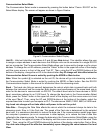
Power and Signal Connections
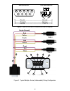
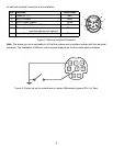
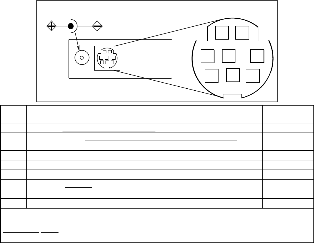
Power can be supplied to your M or V Series meter through either the power jack or the 8 pin Mini-DIN
connector as shown in Figure 1. An AC to DC adapter which converts line AC power to DC voltage
between 7 and 30 volts is required to use the power jack. The adapter current should be at least 100mA.
The power jack accepts 2.1 mm female power plugs with positive centers. Cables and AC/DC adaptors
may purchased from Apex (see Accessories page 42) and are commonly available at local electronics
suppliers. Alternatively, power can be supplied through the Mini-DIN connector as shown below:
7 8
1 2
3
4 5
AC/DC Adapter Jack
6
1
3
2
4 5
6
7
8
Pin Function
Mini-DIN
cable color
1 Inactive or 4-20mA Primary Output Signal Black
2
Static 5.12 Vdc or Secondary Analog Output (4-20mA, 5Vdc, 10Vdc) or
Basic Alarm
Brown
3 RS-232 Input Signal Red
4 Analog Input Signal = Remote Tare (Ground to Tare) Orange
5 RS-232 Output Signal Yellow
6 0-5 Vdc (or 0-10 Vdc) Output Signal Green
7 Power In (7-30 Vdc, 100mA) or (15-30Vdc for 4-20mA units) Blue
8 Ground (common for power, communications and signals) Purple
Note: The above pin-out is applicable to all the ow meters and controllers available with the Mini-
DIN connector. The availability of different output signals depends on the ow meter options ordered.
Underlined Items in the above table are optional congurations that are noted on the unit’s
calibration sheet.
Figure 1. 8 Pin Mini-DIN Connector
CAUTION:Do not connect power to pins 1 through 6 as permanent damage can occur!
Note: Upon initial review of the pin out diagram in Figure 1, it is common to mistake Pin 2 (labeled
5.12 Vdc Output) as the standard 0-5 Vdc analog output signal! In fact Pin 2 is normally a constant
5.12 Vdc that reects the system bus voltage and can be used as a source for the input signal.