


5
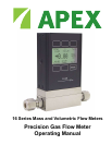
Thank you for purchasing an Apex Gas Flow Meter. Please take the time to nd and read the information
contained in this manual. This will help to ensure that you get the best possible service from your
instrument. This manual covers the following Apex instruments:
M Series 16 Bit Mass Gas Flow Meters
V Series 16 Bit Volumetric Gas Flow Meters
Installation
Plumbing
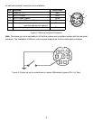
All M or V Series Gas Flow Meters are equipped with female inlet and outlet port connections. Because
the ow meters set up a laminar ow condition within the ow body, no straight runs of pipe are required
upstream or downstream of the meter. The inlet and outlet ports are equal in size and symmetric (in-
line). The port sizes (process connections) and mechanical dimensions for different ow ranges are
shown on pages 29-32.
Meters with 10-32 ports have o-ring face seals and require no further sealant or tape. On other meters,
avoid the use of pipe dopes or sealants on the ports as these compounds can cause permanent damage
to the meter should they get into the ow stream. Use of thread sealing Teon tape is recommended to
prevent leakage around the threads. When applying the tape, avoid wrapping the rst thread or two to
minimize the possibility of getting a piece of shredded tape into the ow stream. When changing ttings,
always clean any tape or debris from the port threads.
It is also recommended that a 20 micron lter be installed upstream of meters with full scale ranges
of 1(S)LPM or less and a 50 micron lter be installed upstream of meters with full scale ranges above
1(S)LPM.
Mounting
All M or V Series Gas Flow Meters have mounting holes for convenient mounting to at panels. These
meters are position insensitive and can be mounted in any orientation. The sizes and dimensions for
the mounting holes are shown on pages 33-35.
Application
Maximum operating line pressure is 145 PSIG (1000 kPa).
Caution: Exceeding the maximum specied line pressure may cause permanent damage to the
solid-state differential pressure transducer.
If the line pressure is higher than 145 PSIG (1000 kPa), a pressure regulator should be used upstream
from the ow meter to reduce the pressure to 145 PSIG (1000 kPa) or less if possible. Although the
meter’s operation is uni-directional, reversing the ow direction will inict no damage as long as the
maximum specied limits are not exceeded.
Note: Avoid installations (such as snap acting solenoid valves upstream) that apply instantaneous
high pressure to the meter as permanent damage to the differential pressure sensor could result.
This damage is not covered under warranty!